Nota Técnica
| Design, development, and implementation of 3D-printed polylactic acid centrifuge rotors for laboratory-scale applications |
|
Luis F. Aiquipa MorenoI; Alexander G. Guillén VasquezI; Elizabeth C. PastranaI,II,*; Roxana Y. PastranaI,#
I. Biomet Research Group, Universidad Nacional de Ingeniería, P.O. Box 31-139, Av. Túpac Amaru 210, Lima, Perú Recebido em: 14/04/2022 *e-mail: epastrana@uni.edu.pe In this work, self-made laboratory centrifuge equipment was developed for the separation of suspensions and immiscible liquids. This centrifuge was based on the Arduino microcontroller and fabricated from simple and recycled mechanical and electronic parts, spending an inexpensive budget suitably. The centrifuge frame and rotors were manufactured of Polylactic Acid (PLA) filaments, which were printed in a 3D printer. Two rotors labeled R50 and R15 were designed and fabricated to use tubes of 50 mL and 15 mL, respectively. The maximum speed reached, without vibration interferences, was 3350 and 3030 rpm for R50 and R15 rotors, respectively. The total fabrication cost of the fabricated centrifuge was less than 100 USD and the assembly process was not complicated. Finally, the centrifuge performance was evaluated through phases of separation of precipitate of CuCO3(s) and clinical blood samples. The obtained results showed achievement in components separation, entirely comparable with those obtained employing a commercial centrifuge. INTRODUCTION A centrifuge is one of the most frequently used instruments in chemistry, biology, biochemistry, and medical laboratories. This equipment applies centrifugal forces to the fluids inside the containers to separate their components (according to particle size, density, viscosity, and rotor speed). In research, the centrifuge is very useful to purify cells,1 subcellular organelles,2 viruses, proteins, and nucleic acids.3 The principle of centrifugation is the centrifugal force (F) subjected to a particle when it is rotated at a high rate of speed. The centrifugal force is defined by the equation (1), where F is the intensity of the centrifugal force, m is an effective mass of the settling particle, ω is the angular velocity of rotation and r is the distance of the migrating particles from the central axis of rotation.4,5  The basic instrumentation centrifuge consists of two components: an electric motor with a drive shaft to spin the sample and the rotor which holds tubes or containers with the sample. There are multiple types of centrifuges, which can be classified by the intended use or by rotor design. Nowadays, exist a wide variety of centrifuges available on the market are ranging from the low-speed centrifuge, high-speed centrifuges, and ultracentrifuges.6 Low-speed centrifuges, also called clinical centrifuges, have a maximum speed in the range of 4000 to 5000 rpm (revolutions per minute) and are the best-selling. Therefore, this equipment becomes important as a tool for research in fundamental laboratories; at present, the clinical centrifuge is commercially affordable although rather expensive (usually between 500 - 900 USD), likewise, an additional expense is required for their maintenance or repair, which increases the cost. Recently, special attention has been focused on the use of microcontroller boards, including Arduino, for the fabrication of low-cost laboratory equipment.7 Arduino has been used in recent years typically in the processing and manufacturing industry, commonly as a tool to improve automated processes or control manufacturing equipment.8 Besides, it is a powerful prototyping device that allows electronics engineers to test the design in a simple and versatile strategy.9 On the other hand, three-dimensional (3D) printing is making remarkable changes in multiple fields of science and technology, including chemistry (organic chemistry, biochemistry and biotechnology, analytical chemistry, pharmaceutics, and chemical education).10 Different published reviews show the use of 3D printing in relevant areas, for instance, natural sciences,11 optical sensing,12 biosensing,13 and microfluidics sensing.14 Fused Deposition Modeling (FDM) is the cheapest (the cost of FDM printers is about 1000 USD) and the simplest method of 3D printing.15 FDM method consists of manufacturing prototypes, according to the computer model, from produced molten filaments. The prototype is formed layer by layer, which hardens immediately.16 FDM is a popular choice for prototyping mainly for its speed. Besides, allowing to print larger objects or an easily scalable design, meaning a low cost-to-size ratio. Likewise, FDM printers accept a wide range of filament materials, such as acrylonitrile butadiene styrene (ABS), polyethylene terephthalate glycol (PETG), polylactic acid (PLA), and nylon.17 In this paper, a low-cost and portable centrifuge was fabricated using a recycled outdoor motor from an air conditioner and an Arduino microcontroller for less than 100 USD. The low-cost frame designed was 3D printed from PLA filaments, classified as one of the most popular materials for 3D printing.18 Furthermore, the equipment fabricated could be used with two different centrifuge rotors for samples of 15 mL and 50 mL capacity, unlike most low-cost commercial centrifuges. Based on this, the fabricated centrifuge works in the speed range of 500-5000 rpm with a power supply of 220 V. The system is configured through a keyboard on the front of the frame. The centrifuge works autonomously once the parameters are entered, for example, speed and working period. Consequently, the centrifuge becomes practical and accessible, making unnecessary the use of computers, telephones, or other additional devices for its operation. In order to confirm our self-build device's performance, it was used in the centrifugation process of liquid suspension samples (CuCO3 and human blood) spinning in tubes at high speed. The high-quality separation obtained, besides the easy handling due to a simple to navigate control panel in the centrifuge represents the main equipment benefit. Finally, the accurate description and construction of centrifuge equipment were reported.
MATERIALS AND METHODS Electrical and electronic components The general construction of the fabricated centrifuge in this work is shown in Figure 1. The electrical part of the apparatus consists of an inexpensive recycled AC motor (LG air conditioner; model PC24SQ) controlled by the electronic part conformed by an Arduino microcontroller (SparkFun Electronics, Mega 2560). The software used was Arduino IDE 1.8.13. Other electrical parts used were a Liquid Crystal Display, LCD (Shenzhen Goldtech Electronics Co., Limited 16x2), a knob switch speed control Dimmers HiLetgo 2000 W (Son Day Day Up Store, 50-220 V AC), a switching power supply (Joolonpor, S-60-12 DC 12V 5A), some electrical wires, a PCB universal board, and switches. Details concerning the materials cost as well as recommendations for usage are presented in the Supplementary Material.
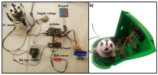 Figure 1. a) Wiring of the Arduino-based centrifuge. b) Arrangement of electrical and electronic components inside on 3D-printed PLA frame centrifuge
The wiring and its arrangement inside the switched-on centrifuge using the electrical and electronic parts described above are shown in Figure 1a and Figure 1b, respectively. Except for the wires, the other parts of the figure were attached through glue on the solid PLA frame (Figure 1b). An Arduino has the role of reading and writing both digital and analog values and states, unlike a microprocessor that can connect directly to switches, buttons, LCDs, LEDs, relays, and serial ports. Thereby, the Arduino could control the speed, time, and AC motor rotation direction with accuracy. The AC motor for our centrifuge, seated on a series of magnets, is controlled by a series of coils that as they are energized the magnetic field produce between them induces an electric current in the rotor. This current produces a magnetic field that tries to oppose what caused it, in this case, the magnetic field generated by the outer coils. The interaction between these two fields causes the rotor can rotate. On the other hand, to drive and control the AC motor speed, an electronic speed dimmer controller (HiLetgo 2000 W) was used. Besides, to measure the speed of the AC motor, a Hall sensor and two neodymium magnets adhered to the side of the rotor were used. In every revolution, the Hall sensor receives two signals due to the presence of the neodymium magnet. With the rotation of the AC motor and the counting of the received signals by the Hall sensor, the motor speed can be calculated by the equation (2):19  Where speed is the revolutions per minute, Nsignal is the number of signals received by the Hall sensor in 1 s, and n is the number of magnets. The maximum speed of the AC motor was 10580 rpm. By mounting the rotors on the motor, the maximum speed decreased to 3350 and 3030 rpm for the rotor for 50 mL tubes (R50) and the rotor for 15 mL tubes (R15) respectively, as a consequence of the rotor mass added to the motor. The speed rotation of the rotors was measured using a tachometer. Mechanical components The mechanical part of the centrifuge involves both the rotor and the frame, where the latter contains the rest of the electrical and electronic components of the equipment. Each part of the centrifuge structure in a real proportion model was designed and the complete simulation assembly test was developed by using Autodesk Inventor 2022 program. Then, the centrifuge frame was fabricated in PLA using a 3D printer. Figures 2a and 2b show the images of the centrifuge pieces designed employing Inventor program and the real photo of the centrifuge already fabricated, respectively. The detailed instructions for assembling the mechanical part along with the two rotors are available in the Supporting Information.
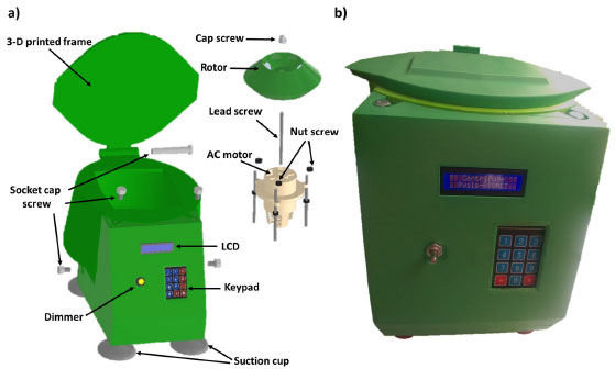 Figure 2. a) 3D schematic design of the centrifuge and, b) 3D-printed Centrifuge with AC motor inside
The main body of the centrifuge The body of the centrifuge was made in PLA using a 3D printer. Three parts were fabricated. The first was the chamber which contains the electrical, electronic, and mechanical pieces. Then, the frontal frame, where the dimmer, LCD screen, and keypad were placed; and finally, the lid. All these pieces were put together through screws. The pieces that conform to the PLA frame of the centrifuge and the lateral-back view of the frame assembled are shown in Figures 3a and 3b, respectively.
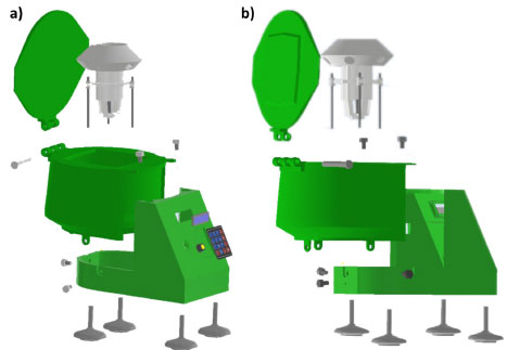 Figure 3. a) Pieces that conform to the frame PLA and b) lateral-back view of the PLA frame assembled to the centrifuge
Rotor geometry The centrifuge rotors were fabricated using 3D printing. The creation of 3D printed rotors is achieved using additive processes. In an additive process, an object is created by laying down successive layers of polylactic acid (PLA) until the object is created. Figure 4 shows the two fabricated rotors in this research (R50 and R15), named based on the volume of the tubes used for centrifugation.
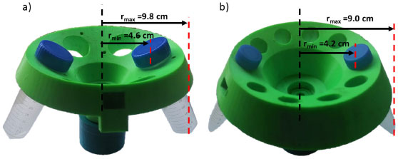 Figure 4. 3D-printed rotors for: a) 50 mL tubes (R50) and b) 15 mL tubes (R15)
Code To set the parameters desired for the built centrifuge, an Arduino code was developed. The user will be able to enter the values of speed and duration using the knob of the dimmer and the keypad, respectively. Then, both values will be displayed on the LCD. After that, the code receives the orders and computes them, adjusting the rotation speed of the AC motor and spinning until the time settled for the centrifugation process ends. The Arduino code used in this research is available in the Supporting Information.
TESTING THE CENTRIFUGE Performance experiment To determine the system performance, different samples of suspensions and immiscible liquids were placed in tubes and spun at high speed. As a consequence of the radial acceleration applied, the heavier particles settle to the tube bottom, while at the same time a slighter substance rise to the top. The force applied to the tubes depends on the diameter of the centrifuge motor. Another important parameter to consider in the centrifugation process is the relative centrifugal force (RCF) or g-force which can be calculated by the equation (3):20  Where r and rpm are the radio of the rotors in centimeters and the value of the revolution per minute of each rotor, respectively. RCF values calculated by equation (3) for the R50 and R15 rotors are presented in Table 1. As shown in Table 1, the R50 rotor has a higher RCF value than the R15 mainly due to rpmMAX.

The centrifuge performance test was carried out by two samples separation and the obtained results are shown in Figure 5. In the first test, a mixed solution of sodium carbonate (Na2CO3, 1 mol/L) and copper sulfate (CuSO4, 1 mol/L) was prepared. Immediately upon these solutions are mixed, the suspension was ready for centrifugation. By placing the suspension in the tube (50 mL) and running the centrifuge using the R50 rotor for 3 min, the color of the aqueous solution changes to pale green which is in the form of precipitate (CuCO3), as shown in Figure 5a. Thus, by writing the balanced chemical equation (4), a double displacement reaction is presented below.
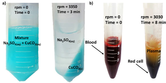 Figure 5. Phase separation through the fabricated centrifuge before and after the centrifugation process for (a) CuCO3 precipitate and (b) human blood using the R50 and R15 rotor, respectively
 In the same way, the second test was made from the separation of red blood cells, platelets, and plasma as routinely practical for blood component analysis as a key diagnostic in the detection of diseases. In this experience, the centrifuge R15 rotor was used for a time of 8 min. The obtained result reveals a complete separation of the plasma as observed in Figure 5b. HAZARDS The circuits of the centrifuge use a low voltage (12 V, 0.5 A); thus, no electrical shock risk exists. Therefore, electrical safety measures have been taken as using electrical tape to insulate all wires and electrical pieces. Besides, due to the PLA, being used as the material for the frame, and the other components that conform to the centrifuge are burnable, they should be handled with care and kept away from heat, hot surfaces, flames, sparks, and other ignition sources. On the other hand, since the PLA is a biodegradable material, we recommend fixing the centrifuge in a work area to avoid splashes from external to the structure and unnecessary handling. The centrifuge should be seated on a firm, not sloped surface. Finally, it would be appropriate to wear personal protective equipment for handling it.
CONCLUSIONS A 3D-printed low-cost centrifuge Arduino-based was fabricated from an AC motor recycled from an air conditioner and other no expensive components. The total fabrication cost of this equipment was less than 100 USD. The centrifuge is capable to use 50 mL and 15 mL tubes placed in 3D-printed rotors labeled R50 and R15, respectively. The maximum speed reached was 3350 and 3030 rpm for R50 and R15 rotors respectively, left out vibrations and controlled by the AC motor. The user can start immediately once the desired parameters such as time and speed of centrifugation are entered. The phase separations using a centrifugation process of precipitate and human blood were developed with success in expected times. The obtained results in this research are repeatable and consistent with the results achieved using a conventional centrifuge. The great advantage of the fabricated centrifuge in this work is the possibility of using different rotors for different volumes of tubes, which makes it a versatile centrifuge that can be adapted to the needs of the user. Besides, this equipment can be constructed by students, where the operation is familiar and simple for untrained personnel. Finally, the simple and economic fabrication of a centrifuge was achieved, as well as an improvement in the knowledge of the simple device's construction based on programming. SUPPLEMENTARY MATERIAL Materials list, wiring circuit, assembling of electrical and mechanical parts, and Arduino code are described in the supplementary material, freely available at http://quimicanova.sbq.org.br.
ACKNOWLEDGMENTS The work described in this paper was funded by Vice-Rectorate for research of the National University of Engineering, grant number FC-PF-21-2021. The authors thank Dr. Pierre Ramos Apestegui of the Center for the Development of Advanced Materials and Nanotechnology at the National University of Engineering for his excellent support and advice for the article. Also, the authors thank Yerson S. Asencio Arcos at the National University of Engineering for his important collaboration at the beginning of the project for tests in the mechanical part of this article.
REFERENCES 1. Brasaemle, D. L.; Wolins, N. E.; Curr. Protoc. Cell Biol. 2016, 72, 3. [Crossref] 2. Yang, J. S.; Kim, J. Y.; Lee, J. C.; Moon, M. H.; Anal. Chim. Acta 2019, 1073, 79. [Crossref] 3. Graham, J. Biological centrifugation, 1st ed., BIOS Scientific Publishers Limited: Oxford, 2001. 4. LeFevre, T. B.; Bikos, D. A.; Chang, C. B.; Wilking, J. N.; Soft Matter 2021, 17, 6326. [Crossref] 5. Ghanaati, S.; Mourão, C. F.; Adam, E. H.; Sader, R.; Zadeh, H. H.; Al-Maawi, S.; Int J Growth Factors Stem Cells Dent 2019, 2, 41. [Crossref] 6. Miron, R. J.; Xu, H.; Chai, J.; Wang, J.; Zheng, S.; Feng, M.; Zhang, X.; Wei, Y.; Chen, Y.; Fernando de Almeida Barros Mourão, C.; Sculean, A.; Zhang, Y.; Clin. Oral Invest. 2020, 24, 1171. [Crossref] 7. Castillo-Vilcatoma, D. A.; Loarte, S. J.; Fernandez-Chillcce, A. A.; Pastrana, E. C.; Pastrana, R. Y.; Quim. Nova 2022, 45, 97. [Crossref] 8. Ardiansah, I.; Bafdal, N.; Suryadi, E.; Bono, A.; Int. J. Adv. Sci. Eng. Inf. Technol. 2020, 10, 703. [Crossref] 9. Saleem, S. I.; Zeebaree, S. R. M.; Zeebaree, D. Q.; Abdulazeez, A. M.; Technol. Rep. Kansai Univ. 2020, 62, 1083. 10. Nesterenko, P. N.; Pure Appl. Chem. 2020, 92, 1341. [Crossref] 11. Kalsoom, U.; Nesterenko, P. N.; Paull, B.; Trends Anal. Chem. 2018, 105, 492. [Crossref] 12. Ni, Y.; Ji, R.; Long, K.; Bu, T.; Chen, K.; Zhuang, S.; Appl. Spectrosc. Rev. 2017, 52, 623. [Crossref] 13. Palenzuela, C. L. M.; Pumera, M.; Trends Anal. Chem. 2018, 103, 110. [Crossref] 14. Rusling, J. F.; ACS Sens. 2018, 3, 522. [Crossref] 15. Gupta, V.; Nesterenko, P.; Paull, B.; 3D Printing in Chemical Sciences: Applications across Chemistry, 1st ed., The Royal Society of Chemistry: London, 2019. 16. Stechina, D.; Mendoza, S. M.; Martín, H. D.; Maggi, C. N.; Piovan, M. T.; Matéria (Rio de Janeiro) 2020, 25, e-12617. [Crossref] 17. Salentijn, G. I.; Oomen, P. E.; Grajewski, M.; Verpoorte, E.; Anal. Chem. 2017, 89, 7053. [Crossref] 18. Stabile, L.; Scungio, M.; Buonanno, G.; Arpino, F.; Ficco, G.; Indoor Air 2016, 27, 398. [Crossref] 19. Sadegh-cheri, M; J. Chem. Educ. 2020, 97, 2338. [Crossref] 20. Miron, R. J.; Pinto, N. R.; Quirynen, M.; Ghanaati, S; J. Periodontol. 2019, 90, 817. [Crossref] |
On-line version ISSN 1678-7064 Printed version ISSN 0100-4042
Qu�mica Nova
Publica��es da Sociedade Brasileira de Qu�mica
Caixa Postal: 26037
05513-970 S�o Paulo - SP
Tel/Fax: +55.11.3032.2299/+55.11.3814.3602
Free access

