Artigo
| Syngas production from CO2-Reforming of CH4 over sol-gel synthesized Ni-Co/Al2O3-MgO-ZrO2 nanocatalyst: effect of ZrO2 precursor on catalyst properties and performance |
|
Seyed Mehdi SajjadiI,II; Mohammad HaghighiI,II,*; Farhad RahmaniI,II
IChemical Engineering Faculty, Sahand University of Technology, P.O.Box 51335-1996, Sahand New Town, Tabriz, Iran Recebido em 09/05/2014 *e-mail: haghighi@sut.ac.ir Ni-Co/Al2O3-MgO-ZrO2 nanocatalyst with utilization of two different zirconia precursors, namely, zirconyl nitrate hydrate (ZNH) and zirconyl nitrate solution (ZNS), was synthesized via the sol-gel method. The physiochemical properties of nanocatalysts were characterized by XRD, FESEM, EDX, BET and FTIR analyses and employed for syngas production from CO2-reforming of CH4. XRD patterns, exhibiting proper crystalline structure and homogeneous dispersion of active phase for the nanocatalyst ZNS precursor employed (NCAMZ-ZNS). FESEM and BET results of NCAMZ-ZNS presented more uniform morphology and smaller particle size and consequently higher surface areas. In addition, average particle size of NCAMZ-ZNS was 15.7 nm, which is close to the critical size for Ni-Co catalysts to avoid carbon formation. Moreover, FESEM analysis indicated both prepared samples were nanoscale. EDX analysis confirmed the existence of various elements used and also supported the statements made in the XRD and FESEM analyses regarding dispersion. Based on the excellent physiochemical properties, NCAMZ-ZNS exhibited the best reactant conversion across all of the evaluated temperatures, e.g. CH4 and CO2 conversions were 97.2 and 99% at 850 ºC, respectively. Furthermore, NCAMZ-ZNS demonstrated a stable yield with H2/CO close to unit value during the 1440 min stability test. INTRODUCTION A mixture of H2 and CO which is known as syngas is an important feedstock in the production of petrochemical. It plays the key role as an intermediate to convert natural gas to liquid fuel via Fischer-Tropsch synthesis.1,2 Syngas can be produced by various processes such as steam reforming, partial oxidation and CO2-reforming of methane.3-6 Among them, CO2-reformingof methane (reaction (1)) or dry reforming of methane (DRM) has shown an increasing interest in recent years because of the following striking features: (i) converting two major greenhouse gases (CO2 and CH4) to syngas with H2/CO ratio close to 1 which is desirable for synthesis of higher hydrocarbons and oxygenated derivatives (ii) exploitation of natural gas resources with high CO2 content, avoiding the expensive and intricate gas separation process.7-9  It must be noted that DRM reaction is also influenced by other side reactions which simultaneously occur. They are as follow: Reverse water gas shift reaction (RWGS (2)) which causes the H2/CO ratio less than unity. Methane decomposition (3) and Boudouard reactions (4) which take place and lead to carbon deposition and subsequently catalyst deactivation. This is the major obstacle preventing commercialization of DRM.10-12  The catalytic performance of the numerous supported catalysts has been evaluated for DRM, especially nickel and noble metal-based catalysts.13-17 Although coke formation is more probable in the case of nickel based catalysts than the noble metals, based on the higher availability and lower cost of nickel based ones, they have received more attention.18,19 According to the literature, alumina is more common support for Ni-based catalysts which its chosen is attributed to the high surface area, high mechanical strength and low price.20-22 Therefore, conventional catalyst for DRM is Ni/Al2O3 which quickly deactivates due to coke formation.23 Up to now, the development of DRM has been hindered by the absence of suitable catalyst that provides high activity and selectivity.24 On the other hand, lower coke formation and proper catalytic performance is attributed to excellent physiochemical properties such as uniform and small particle size distribution and strong metal-support interaction (SMSI). Therefore, different parameters which are effective on superior characterization and consequently better catalytic performance such as preparation method, metal content and addition of promoters have been studied.25-29 Sol-gel technique is a useful method for production of more uniform composition and controlling particle size distribution in nanoscale level.30,31 So, attainment of the nanocatalysts with appropriate catalytic performance is probable by utilization of this method.30,31 Hao et al. verified Ni/Al2O3 catalysts prepared via sol-gel method combined with a supercritical drying process represent the better catalytic performance than the ones synthesized via impregnation method.32 Moreover, it was reported that improving active phase by addition of promoters such as Co, Cu, Sn, K and Ca leads to the superior catalytic performance.33-36 Addition of K and Ca divides the Ni surface into small ensembles, maintaining them less prone to coking.27 Co has similar electronic configuration to Ni and may control the size of Ni ensembles and alter the size of active sites of Ni causing carbon formation to be suppressed. Furthermore, Co addition leads to high dispersion of the active phase and strong metal-support interaction (SMSI) in the case of Ni-Co bimetallic catalyst.37 It must be noted that the superior performance of Ni-Co bimetallic catalysts was found for 3-5 wt.% of Co, especially in the case of Co/Ni≈0.5 (weight ratio).37-39 Several authors have been reported Ni/MgO catalysts present good stability in DRM as a result of their pronounced surface basicity and high metal dispersion.33,40,41 However, MgO has relatively low specific area. Therefore, a mixed framework of Al2O3-MgO is proposed with the consideration of the high thermal stability of MgO and the high specific surface area of Al2O3.7,42,43 Addition of small amounts of MgO to Ni/ZrO2 leads to the better dispersion of Ni and increasing the basicity of the support.44 Zirconia has been recently used as either a promoter or a support for Ni in DRM.42,45 Moreover, due to the excellent redox properties, they are able to improve the stability of the catalyst under both oxidizing and reducing atmospheres which is the main reason of its utilization.46 As a result of this, zirconia promotes the gasification of adsorbed intermediates which are precursors of carbon formation and responsible for the main deactivation mechanism in DRM.47-49 Furthermore, owning to the mentioned redox properties, ZrO2 can be a feasible candidate for structural and chemical stabilizer of transition Al2O3.46 CO2-reforming of CH4 by utilization of various preparation methods and applying a variety of supports and active phases was evaluated which some of them were mentioned above. However, according to the literature review, synthesis and utilization of Ni-Co/Al2O3-MgO-ZrO2 nanocatalyst with various zirconia precursors for DRM has not been reported in the literature. So, we make an effort to investigate these nanocatalysts for DRM. In this paper, Ni-Co/Al2O3-MgO-ZrO2 nanocatalysts with utilization of different zirconia precursors were prepared via sol-gel method and used for DRM. The nanocatalysts were characterized using XRD, FESEM, FTIR, EDX and BET analyses. Finally, the effect of zirconia precursor on the catalytic performance of the prepared nanocatalysts toward DRM was evaluated.
EXPERIMENTAL Materials Al-tri-sec-butoxide, zirconyl nitrate solution (ZNS), zirconyl nitrate hydrate (ZNH) and Mg(NO3)2.6H2O were employed as support precursors. Ni(NO3)2.6H2O and Co(NO3)2.6H2O were used as active phase and promoter precursors, respectively. Isopropanol and acetylacetone were used as solvent and chelating agent, respectively. All of the materials were purchased from Merck Company. Nanocatalyst preparation and procedures Schematic flowchart for the preparation steps of Ni(10 wt.%)-Co(5 wt.%)/Al2O3-MgO-ZrO2 nanocatalysts is illustrated in Figure 1. The nanocatalysts were prepared via sol-gel method with different MgO and ZrO2 loadings. The samples which employed ZNS and ZNH were denoted as NCAMZ-ZNH and NCAMZ-ZNS, respectively. At first, Al-tri-sec-butoxide, Mg(NO3)2.6H2O and zirconia precursor (ZNS or ZNH regarding to type of synthesized sample) were dissolved in appropriate amount of isopropanol. Next, acetylacetone was added as chelating agent. The solution of support precursor was vigorously stirred at room temperature (in N2 atmosphere) for 30 min. In the second step, Ni-Co precursor was prepared by dissolving appropriate proportion of Ni(NO3)2.6H2O and Co(NO3)2.6H2O in deionized water, which was named active phase solution. Subsequently, the active phase solution was added dropwise under mild stirring. The resulting gel was aged for 5 days at room temperature and dried at 60 ºC for another 5 days. After calcination at 600 ºC for 5 h, the nanocatalysts were formed and shaped to be used in performance tests.
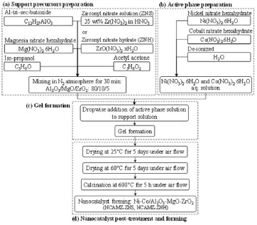 Figure 1. Sol-gel synthesis steps of Ni-Co/Al2O3-MgO-ZrO2 nanocatalyst
Nanocatalyst characterization techniques The structure of catalysts was assessed using XRD analyzer (D5000 Siemens, Germany). The conditions of analysis were as follows: Cu-Ka radiation; scanning rate: 0.03º s-1; scanning range (2θ): 20-90º. The morphology and particle size of the nanocatalysts were observed by Field Emission Scanning Electron Microscopy (FESEM) analyzer (HITACHI S-4160, Japan). In order to confirm the presence of metals and study of dispersion, Energy dispersive X-ray (EDX) analysis was conducted. The BET surface area of the catalysts was measured by N2 adsorption at liquid-nitrogen temperature, using a surface area analyzer (Quantachrome chembet-3000, America). Investigation on functional groups of the synthesized nanocatalysts was carried out by Fourier Transform Infrared Spectroscopy (FTIR, UNICAM 4600) in the range of 400-4000 cm-1 wave number. Experimental setup for catalytic performance test Utilized experimental setup for activity measurement of the synthesized nanocatalysts consists of a gas feeding section, a fixed bed reactor, and an analytical section. Prior to catalytic activity tests, all catalysts were reduced for 4 h in hydrogen at a flow rate of 30 cm3/min and 700 ºC. The catalytic performance of nanocatalysts was investigated in the atmospheric pressure, stoichiometric feed ratio, GHSV of 24 l/gcat h and temperature range from 550 to 850 ºC. The reaction was performed at U-shaped quartz reactor with 6 mm internal diameter mounted vertically inside a tubular furnace. The quartz micro reactor was charged with 0.1 g of calcined catalyst and surrounded by chips to maintain the bed in the desired location. Heating rate of nanocatalyst was 10 ºC per minutes. Stability tests were performed at 850 ºC for 1440 min. The reaction products were sent to an online gas chromatograph (GC Chrom, Teif Gostar Faraz, Iran). Employed column for separation of gaseous was Carboxen-1000. To ensure reproducibility of the results, the experiments were repeated under similar conditions several times. Blank runs showed no conversion in the range of reaction temperatures. The conversion of reactants and products yield is calculated as follows: 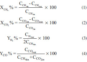 where Ci,in/out is the flow rate of each component in the feed or effluent.
RESULTS AND DISCUSSIONS Nanocatalyst characterization XRD analysis Figure 2 exhibits the XRD patterns of synthesized Ni-Co/Al2O3-MgO-ZrO2 nanocatalysts at 2θ = 20-90º. Existence of some peaks upon to these patterns were revealed at 2θ = 37.3, 43.4, 63, 75.6 and 79.6º (JCPDS 01-073-1519) and at 2θ = 31.3, 36.9, 38.6, 44.9, 55.7, 59.4 and 65.3º (JCPDS 01-075-1802), which might be attributed to the NiO and Co3O4 cubic phases, respectively. Moreover, peaks at 2θ = 37.4, 42.8, 45.7 and 67.3º (JCPDS 00-004-0880) could be assigned to cubic Al2O3 phases. Furthermore, cubic MgO peaks are observed at 2θ = 37.0, 42.9, 62.4, 74.8 and 78.1º (JCPDS 01-077-2364). Comparing XRD patterns of synthesized samples revealed NCAMZ-ZNS has a suitable crystalline structure which improves catalytic activity. In contrast, the clear crystalline behavior was not indicated in the case of NCAMZ-ZNH. Crystallinity reduction for ZrO2-Al2O3 mixture was reported by other researchers. They declared that adding ZrO2 to Al2O3 may lead to formation of ZrO2-Al2O3 solid solution which is in amorphous phase or if it is in crystalline phase, the crystal size are too small to be detected by the XRD technique. This might be contributed to the appropriate acidic pH (ranging from 5 to 5.5) of environment which will be explained in FESEM section. Furthermore, they addressed these observations to the lower calcination temperature or uniformly ZrO2 dispreading.48,50,51 Although, regarding to the used calcination temperature (600 ºC), formation of NiAl2O4, CoAl2O4, and MgAl2O4 spinel phases is probable, these structures are hardly distinguishable by XRD patterns due to their similarity and peaks overlap.2,52 However, comparing the diffraction patterns with JCPDS 00-010-0339 and JCPDS 00-001-1157 demonstrated the existence of some peaks which probably are related to the NiAl2O4 and MgAl2O4, respectively. Garcia et al. reported that addition of small amounts of MgO to Ni/ZrO2 catalyst leads to stabilization of the zirconia tetragonal phase by increasing its thermal stability.44 According to their claim and JCPDS 00-004-0880, the peaks represented at 2θ = 30.2, 50.3, 50.7 and 60.2º might be attributed to the zirconia tetragonal phase. Based on the investigation conducted in the field of MgO promoted Ni/Al2O3 and Ni/ZrO2 catalysts, strong interaction between active phase and support was obtained. Furthermore, as the Mg content increases, SMSI which leads to the more uniform dispersion of the active phase, enhances.44,53-55 Based on our previous researches and some other investigations, 25 wt% MgO was used for both samples in this study.56,57 However, it inferred that small amount addition of ZrO2to Al2O3 might be led to improved metallic dispersion, higher reducibility and improvement of thermal stability. But it must be noted that the high amount of ZrO2 could greatly decrease the surface area of support, leading to low dispersion of nickel particles.48,49 Based on the other researchers' reports, the 5-10% ZrO2 loading seems to be a suitable loading range.49,50,58 Moreover, in our previous work, Ni-Co/Al2O3-MgO nanocatalyst promoted by 5 wt.%ZrO2represented better catalytic activity and characterization than 10 wt.% and unprompted ones.59 Therefore, it is probable that suitable crystalline structural and promoted dispersion of active phase obtain for ZNS based nanocatalyst. This hypothesis is going to be supported by the FESEM, EDX and BET analyses in the following sections of this paper.
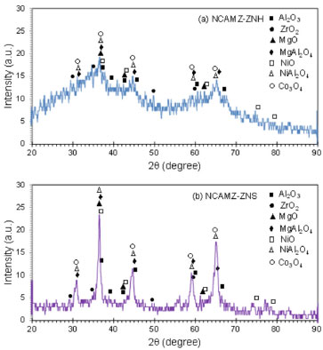 Figure 2. XRD patterns of Ni-Co/Al2O3-MgO-ZrO2 nanocatalysts: (a) NCAMZ-ZNH and (b) NCAMZ-ZNS
FESEM analysis FESEM images of synthesized samples with different zirconia precursors are illustrated in Figure 3. The micrographs are magnified in 300 nm. Images revealed that approximately acceptable particle size distribution was obtained for all prepared samples. Moreover, the images exhibited that NCAMZ-ZNS represents smaller particle size and more uniform distribution. This discrepancy is related to the different nature of zirconia precursors. In synthesis of NCAMZ-ZNS, acidity of the system increases by peptization of zirconyl nitrate in nitric acid. Under acidic conditions, hydrolysis occurs at a faster rate than condensation, and the resulting gel is weakly branched. At a pH well below the pHIEP (IEP: isoelectric pH), the surface of support would have a net positive charge yielding a nonaggregated and stable sol.31,60 Thus, uniform morphology is obtained after drying the gel for NCAMZ-ZNS. These results are in agreement with the mentioned claim in XRD analysis, which noted better dispersion belongs to NCAMZ-ZNS. To scrutiny of the effect of zirconia precursor type on the morphology of prepared nanocatalysts, the particle size distribution was evaluated by Image-J software. Outcomes were depicted in histogram diagrams of Figure 3. It specifies that both samples are nanoscale and there is no particle larger than 34.1nm. The average particle size for NCAMZ-ZNS and NCAMZ-ZNH are 15.7 and 18.3 nm, respectively. Furthermore, in the case of NCAMZ-ZNS, approximately 99% of particles are less than 30 nm. Therefore, superior particle size distribution and smaller average particle size was obtained for NCAMZ-ZNS. These results are in agreement with XRD analysis.
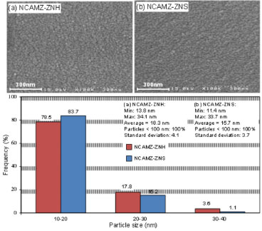 Figure 3. FESEM images size distribution histogram of Ni-Co/Al2O3-MgO-ZrO2 nanocatalysts: (a) NCAMZ-ZNH and (b) NCAMZ-ZNS
EDX analysis Figure 4 shows the results of EDX analysis for the prepared Ni-Co/Al2O3-MgO-ZrO2 nanocatalysts. EDX spectra confirmed the existence of the all elements used in the synthesis procedure. The outcomes of this analysis supported the declared assertion about the dispersion of the synthesized nanocatalysts in XRD and FESEM analyses. As depicted in the images, all elements specially Ni and Co are uniformly dispersed over the nanocatalysts surface. Briefly, the outcomes of EDX analysis exhibited: (i) acceptable dispersion was obtained for both prepared samples. (ii) NCAMZ-ZNS presented the better dispersion which is going to affect the catalytic process.
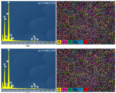 Figure 4. EDX analysis of Ni-Co/Al2O3-MgO-ZrO2 nanocatalysts: (a) NCAMZ-ZNH and (b) NCAMZ-ZNS
BET analysis Owning to the important effect of high surface area in promotion of reactants adsorption which is one of the main steps of heterogeneous catalytic reaction, surface area of prepared nanocatalysts was measured. The surface area of NCAMZ-ZNS and NCAMZ-ZNH are 51.0 and 37.4 m2 g-1, respectively. These results indicate that higher surface area was obtained for ZNS based nanocatalysts. This might be derived of the effect of peptization noted in FESEM section and led to the more uniform dispersion and smaller particle size distribution. This observation is in agreement with the results of FESEM and XRD analyses. FTIR analysis FTIR spectra of the synthesized samples were recorded in the 400-4000 cm-1 range and acquired results are depicted in Figure 5. The peak which indicated in 1525 cm-1 is caused by N-O and N-C as a result of atmospheric nitrogen in the lab, residual nitrate compounds such as nickel nitrate and especially nitrogen ambience that is necessary for the synthesis.61 The peak at 2350 cm-1 can be assigned to the asymmetric stretching frequency [υ(CO)] of CO2 which is resulted in the aerial CO2. Furthermore, the IR spectra of all nanocatalysts exhibit M-O, Al-O and M-O-Al (M=Ni, Co, Mg and Zr) stretching frequencies in the range of 470-800 cm-1.62,63 Moreover, the broadening adsorption bands in 3440, 1640 and 1420 cm-1 are attributed to stretching vibration for structural -OH and adsorbed water.61 The appearance of these vibrations is probably due to the absorption of water in all samples after calcination. Presence of OH groups due to their ability in removing the formed coke is very noticeable.64 Moreover, since chelating effect of acetylacetone decrease condensation and consequently rate of gel network formation, very stable sol will be probably obtained by addition of it to aluminum. Therefore, all the metal ions distribute homogeneously. It must be noted pure acetylacetone has the two characteristic peaks between 1620 to 1700 cm-1 assigned to carbonyl group. Since after reacting acetylacetone with aluminum there is no carbonyl group in the FTIR spectra, we can conclude the chelation was good enough to synthesize a stable sol and consequently attain uniform dispersion.65-67
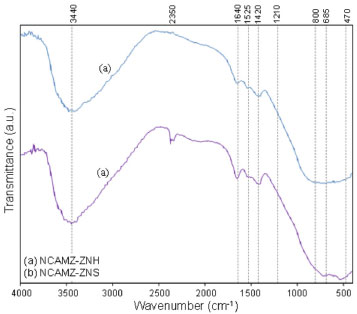 Figure 5. FTIR spectra of Ni-Co/Al2O3-MgO-ZrO2 nanocatalysts: (a) NCAMZ-ZNH and (b) NCAMZ-ZNS
Catalytic performance study toward CO2-reforming of CH4 effect of ZrO2 precursoron feed conversion at different temperatures Feed (CH4 and CO2) conversion of the synthesized nanocatalysts was recorded at constant molar feed ratio, GHSV equal 24 l/gcat and temperature range of 550 to 850 ºC and obtained results are depicted in Figure 6. Diagrams obviously present that ascending temperature enhances the feed conversion for all samples which is related to the endothermic nature of DRM. Moreover, it was found NCAMZ-ZNS represent the better catalytic performance (XCH4=98% and XCO2=97.8% at 850 ºC) compared with the NCAMZ-ZNH. The superior performance of NCAMZ-ZNS is related to its excellent characterization such as smaller particle size, uniform dispersion and higher surface area. Furthermore, feed conversion increase at the higher range of evaluated temperatures is less than lower parts. For example, CH4 conversion for NCAMZ-ZNS at 850 ºC is 98% which is 6.48% better than 750 ºC while the improvement of the conversion for 650ºC and 550 ºC is 26.40%. This trend might derive of variable effect of side reactions at different temperatures and approaching to the equilibrium conversion. Moreover, for both nanocatalysts, CH4/CO2 is less than unit and this ratio increases as reaction temperature rises. This observation might be associated to the occurrence of the side reactions such as RWGS which are affected by reaction temperature and will be discussed in next section.
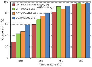 Figure 6. Effect of ZrO2 precursor on feed conversion at different temperatures over synthesized nanocatalysts: NCAMZ-ZNH and NCAMZ-ZNS
Effect of ZrO2 precursor on H2/CO ratio at different temperatures As mentioned previously, production of H2/CO ratio close to 1 is desirable for synthesis of higher hydrocarbons and oxygenated derivatives. So, this subject is considered as one of the main goals of DRM. Accordingly, H2/CO ratio for synthesized nanocatalysts was investigated and outputs were illustrated in Figure 7. The obtained results proved that NCAMZ-ZNS represented higher syngas production and more close to unit H2/CO ratio in all of the investigated temperature rang. Figure 7 shows that H2/CO for NCAMZ-ZNS at 650 ºC and 750 ºC are 82% and 97%, respectively. In addition, this ratio is approximately unit at 850 ºC. As noted above, better performance of NCAMZ-ZNS is attributed to its superior physiochemical properties such as smaller particle size, uniform dispersion and higher surface area which were attained due to the utilization of the better zirconia precursor. However, H2/CO ratio for NCAMZ-ZNH until 650 ºC is lower than 0.80 and just at 850 ºC is moving toward unity. Furthermore, for both nanocatalysts, H2/CO is less than unit and this ratio approaches toward unity as temperature rises. This behavior is related to the influence of the reaction temperature on the rate of side reactions such as RWGS which occur simultaneously with main reaction of DRM. On one hand, methane cracking reaction accelerates by temperature increasing which leads to the easy decomposition of C-H bonds at higher temperatures. On the other hand, the exothermic RWGS reaction is favored with decreasing temperature. Thus, as the temperature rises, H2 yield and CH4 consumption increase. However, CO yield and CO2 consumption reduce. Therefore, at higher temperatures, the conversion of CH4 and CO2 are approaching to each other and CH4/CO2 is moving toward unity.
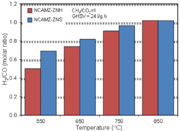 Figure 7. Effect of ZrO2 precursor on H2/CO molar ratio at different temperatures over synthesized nanocatalysts: NCAMZ-ZNH and NCAMZ-ZNS
Time on stream performance According to literature, one of the important requirements for the competitive commercial reforming catalysts is high stability and resistance to deactivation by coke.40,68 Therefore, reactants conversion and H2/CO of the NCAMZ-ZNS and NCAMZ-ZNH were tested at 850 ºC, GHSV=24 l/gcat h and equimolar feed ratio during1440 min time on stream. Recoded results are shown in Figure 8. The graphs demonstrated that there was no significant deactivation for none of prepared nanocatalysts. On the hand, it is known that particle size and their distribution and also SMSI are effective parameters in the rate of carbon deposition. On this basis, the rate of deactivation is dependent on the factors that influence these parameters. Therefore, acceptable stability of samples might be related to the utilization of sol-gel method which is an appropriate method for preparation of high homogeneity composition and smaller particle size distribution.30 Moreover, this behavior probably is related to the addition of cobalt. Synergy of Ni-Co leads to the enhanced SMSI, separation of metal ensembles in smaller metal particles and reduction of carbon deposition.48,69 A detailed examination indicates NCAMZ-ZNS illustrated the best performance by representing reactants conversion in the range of 97.2-99% and also H2/CO ratio close to unit at 850 ºC during 1440 min. Moreover, beside the appropriate synthesis method and suitable active phase promoter, the catalytic performance will be enhanced via employment of proper support promoters. In the case of NCAMZ-ZNS, utilization appropriate zirconia precursor altered the characterization. Therefore, in agreement with FESEM, BET and EDX analyses, surface area increased, uniform particle size distribution was obtained and finally high and stable catalytic performance was observed. However, it should be noted that to assess the nanocatalyst durability, long-term stability tests and more investigations are required.
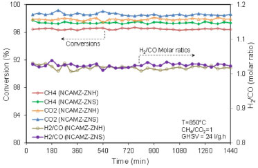 Figure 8. Time on stream performance of synthesized nanocatalysts: NCAMZ-ZNH and NCAMZ-ZNS
CONCLUSIONS XRD, FESEM and EDX analyses illustrated f appropriate crystalline structural and uniform dispersion of active phase for Ni-Co/Al2O3-MgO-ZrO2 nanocatalyst which employed ZNS precursor. FESEM analysis remarked all samples are nano scale. Also, smaller particle size and more uniform morphology of NCAMZ-ZNS were demonstrated by FESEM analysis. EDX analysis verified the existence of various elements and supported the noted assertion in XRD and FESEM analyses about the dispersion. Moreover, higher surface area of NCAMZ-ZNS was presented by BET analysis. Superior characterization of NCAMZ-ZNS, leads to the excellent reactants conversion throughout all of the investigated temperatures i.e. CH4 and CO2 conversions at 850 ºC are in the range of 97.2-99%. In addition, NCAMZ-ZNS exhibited the stable yield with H2/CO close to unit during 1440 min stability test. In summary, the appropriate physiochemical properties and thereupon better catalytic performance of NCAMZ-ZNS proposed it as a highly capable catalyst for DRM.
ACKNOWLEDGEMENTS The authors gratefully acknowledge Sahand University of Technology for the financial support of the research as well as Iran Nanotechnology Initiative Council for complementary financial support.
REFERENCES 1. Fan, M.-S.; Abdullah, A. Z.; Bhatia, S.; Appl. Catal., B 2010, 100, 365. DOI: http://dx.doi.org/10.1016/j.apcatb.2010.08.013 2. Xu, L.; Song, H.; Chou, L.; Appl. Catal., B 2011, 108-109, 177. DOI: http://dx.doi.org/10.1016/j.apcatb.2011.08.028 3. Ross, J. R. H.; van Keulen, A. N. J.; Hegarty, M. E. S.; Seshan, K.; Catal. Today 1996, 30, 193. DOI: http://dx.doi.org/10.1016/0920-5861(96)00035-1 4. Vafaeian, Y.; Haghighi, M.; Aghamohammadi, S.; Energy Convers. Manage. 2013, 76, 1093. DOI: http://dx.doi.org/10.1016/j.enconman.2013.08.010 5. Sharifi, M.; Haghighi, M.; Abdollahifar, M.; Mater. Res. Bull. 2014, 60, 328. DOI: http://dx.doi.org/10.1016/j.materresbull.2014.07.027 6. Rahmani, F.; Haghighi, M.; Vafaeian, Y.; Estifaee, P.; J. Power Sources 2014, 272, 816. DOI: http://dx.doi.org/10.1016/j.jpowsour.2014.08.123 7. Aghamohammadi, S.; Haghighi, M.; Karimipour, S.; J. Nanosci. Nanotech. 2013, 13, 4872. DOI: http://dx.doi.org/10.1166/jnn.2013.7588 8. San-José-Alonso, D.; Juan-Juan, J.; Illán-Gómez, M. J.; Román-Martínez, M. C.; Appl. Catal., A 2009, 371, 54. DOI: http://dx.doi.org/10.1016/j.apcata.2009.09.026 9. Serrano-Lotina, A.; Daza, L.; Int. J. Hydrogen Energy 2013, 39, 4089. DOI: http://dx.doi.org/10.1016/j.ijhydene.2013.05.135 10. Horvath, A.; Stefler, G.; Geszti, O.; Kienneman, A.; Pietraszek, A.; Guczi, L.; Catal. Today 2011, 169, 102. DOI: http://dx.doi.org/10.1016/j.cattod.2010.08.004 11. Al-Fatish, A. S. A.; Ibrahim, A. A.; Fakeeha, A. H.; Soliman, M. A.; Siddiqui, M. R. H.; Abasaeed, A. E.; Appl. Catal., A 2009, 364, 150. DOI: http://dx.doi.org/10.1016/j.apcata.2009.05.043 12. Al-Fatesh, A. S. A.; Fakeeha, A. H.; J. Saudi Chem. Soc. 2012, 16, 55. DOI: http://dx.doi.org/10.1016/j.jscs.2010.10.020 13. Rahemi, N.; Haghighi, M.; Babaluo, A. A.; Jafari, M. F.; Estifaee, P.; J. Ind. Eng. Chem. 2013, 19, 1566. DOI: http://dx.doi.org/10.1016/j.jiec.2013.01.024 14. Rahemi, N.; Haghighi, M.; Babaluo, A. A.; Fallah Jafari, M.; Khorram, S.; J. Appl. Phys. 2013, 114, 0943011. DOI: http://dx.doi.org/10.1023/B:PHAM.0000045235.86197.ef PMID: 15553228 15. Li, B.; Xu, X.; Zhang, S.; Int. J. Hydrogen Energy 2013, 38, 890. DOI: http://dx.doi.org/10.1016/j.ijhydene.2012.10.052 16. Bychkov, V. Y.; Tyulenin, Y. P.; Firsova, A. A.; Shafranovsky, E. A.; Gorenberg, A. Y.; Korchak, V. N.; Appl. Catal., A 2013, 453, 71. DOI: http://dx.doi.org/10.1016/j.apcata.2012.12.006 17. Nakagawa, K.; Anzai, K.; Matsui, N.; Ikenaga, N.; Suzuki, T.; Teng, Y.; Kobayashi, T.; Haruta, M.; Catal. Lett. 1998, 51, 163. DOI: http://dx.doi.org/10.1023/A:1019065824331 18. Bradford, M. C. J.; Vannice, M. A.; Appl. Catal., A 1996, 142, 73. DOI: http://dx.doi.org/10.1016/0926-860X(96)00065-8 19. Barroso-Quiroga.; Martha.M.; Castro-Luna.; Eduardo.A.; Int. J. Hydrogen Energy 2010, 35, 6052. DOI: http://dx.doi.org/10.1016/j.ijhydene.2009.12.073 20. Souza, M. M. V. M.; Aranda, D. A. G.; Schmal, M.; J. Catal. 2001, 204, 498. DOI: http://dx.doi.org/10.1006/jcat.2001.3398 21. Estifaee, P.; Haghighi, M.; Babaluo, A. A.; Rahemi, N.; Fallah Jafari, M.; J. Power Sources 2014, 257, 364. DOI: http://dx.doi.org/10.1016/j.jpowsour.2014.01.128 22. Abdollahifar, M.; Haghighi, M.; Babaluo, A. A.; J. Ind. Eng. Chem. 2014, 20, 1845. DOI: http://dx.doi.org/10.1016/j.jiec.2013.08.041 23. Kim, P.; Kim, Y.; Kim, H.; Song, I. K.; Yi, J.; Appl. Catal., A 2004, 272, 157. DOI: http://dx.doi.org/10.1016/j.apcata.2004.05.055 24. Haghighi, M.; Sun, Z.-q.; Wu, J.-h.; Bromly, J.; Wee, H. L.; Ng, E.; Wang, Y.; Zhang, D.-k.; Proc. Combust. Inst. 2007, 31, 1983. DOI: http://dx.doi.org/10.1016/j.proci.2006.07.029 25. Ruckenstein, E.; Wang, H. Y.; J. Catal. 2002, 205, 289. DOI: http://dx.doi.org/10.1006/jcat.2001.3458 26. Tang, S.; Ji, L.; Lin, J.; Zeng, H. C.; Tan, K. L.; Li, K.; J. Catal. 2000, 194, 424. DOI: http://dx.doi.org/10.1006/jcat.2000.2957 27. Osaki, T.; Mori, T.; J. Catal. 2001, 204, 89. DOI: http://dx.doi.org/10.1006/jcat.2001.3382 28. Cai, X.; Cai, Y.; Lin, W.; J. Nat. Gas Chem. 2008, 17, 201. DOI: http://dx.doi.org/10.1016/S1003-9953(08)60052-3 29. Zhang, J.; Wang, H.; Dalai, A. K.; J. Catal. 2007, 249, 300. DOI: http://dx.doi.org/10.1016/j.jcat.2007.03.016 30. Dimitriev, Y.; vanova, Y.; Iordanova, R.; J. Univ. Chem. Technol. Metall. 2008, 43, 181. 31. Gonzalez, R. D.; Lopez, T.; Gomez, R.; Catal. Today 1997, 35, 293. DOI: http://dx.doi.org/10.1016/S0920-5861(96)00162-9 32. Hao, Z.; Zhu, Q.; Jiang, Z.; Hou, B.; Li, H.; Fuel Process.Technol. 2009, 90, 113. DOI: http://dx.doi.org/10.1016/j.fuproc.2008.08.004 33. Nagaraja, B. M.; Bulushev, D. A.; Beloshapkin, S.; Ross, J. R. H.; Catal. Today 2011, 178, 132. DOI: http://dx.doi.org/10.1016/j.cattod.2011.08.040 34. Li, S.; Lu, Y.; Guo, L.; Zhang, X.; Int. J. Hydrogen Energy 2011, 36, 14391. DOI: http://dx.doi.org/10.1016/j.ijhydene.2011.07.144 35. Shi, C.; Zhang, P.; Appl. Catal., B 2012, 115-116, 190. DOI: http://dx.doi.org/10.1016/j.apcatb.2011.12.002 36. Sajjadi, S.; Haghighi, M.; Eslami, A.; Rahmani, F.; J. Sol-Gel Sci. Technol. 2013, 67, 601. DOI: http://dx.doi.org/10.1007/s10971-013-3120-8 37. Zhang, J.; Wang, H.; Dalai, A. K.; Appl. Catal., A 2008, 339, 121. DOI: http://dx.doi.org/10.1016/j.apcata.2008.01.027 38. Xu, J.; Zhou, W.; Li, Z.; Wang, J.; Ma, J.; Int. J. Hydrogen Energy 2009, 34, 6646. DOI: http://dx.doi.org/10.1016/j.ijhydene.2009.06.038 39. Koh, A. C. W.; Chen, L.; Kee Leong, W.; Johnson, B. F. G.; Khimyak, T.; Lin, J.; Int. J. Hydrogen Energy 2007, 32, 725. DOI: http://dx.doi.org/10.1016/j.ijhydene.2006.08.002 40. Ruckenstein, E.; Hu, Y. H.; Appl. Catal., A 1995, 133, 149. DOI: http://dx.doi.org/10.1016/0926-860X(95)00201-4 41. Meshkani, F.; Rezaei, M.; Int. J. Hydrogen Energy 2010, 35, 10295. DOI: http://dx.doi.org/10.1016/j.ijhydene.2010.07.138 42. Yang, M.; Guo, H.; Li, Y.; Dang, Q.; J. Nat. Gas Chem. 2012, 21, 76. DOI: http://dx.doi.org/10.1016/S1003-9953(11)60336-8 43. Fan, M.-S.; Abdullah, A. Z.; Bhatia, S.; Int. J. Hydrogen Energy 2011, 36, 4875. DOI: http://dx.doi.org/10.1016/j.ijhydene.2011.01.064 44. Garcia, V.; Fernandez, J. J.; Ruiz, W.; Mondragan, F.; Moreno, A.; Catal. Commun. 2009, 11, 240. DOI: http://dx.doi.org/10.1016/j.catcom.2009.10.003 45. Zheng, W.-T.; Sun, K.-Q.; Liu, H.-M.; Liang, Y.; Xu, B.-Q.; Int. J. Hydrogen Energy 2012, 37, 11735. DOI: http://dx.doi.org/10.1016/j.ijhydene.2011.03.054 46. Seo, J. G.; Youn, M. H.; Park, S.; Chung, J. S.; Song, I. K.; Int. J. Hydrogen Energy 2009, 34, 3755. DOI: http://dx.doi.org/10.1016/j.ijhydene.2009.03.030 47. Rezaei, M.; Alavi, S. M.; Sahebdelfar, S.; Yan, Z.-F.; Mater. Lett. 2007, 61, 2628. DOI: http://dx.doi.org/10.1016/j.matlet.2006.10.053 48. Therdthianwong, S.; Therdthianwong, A.; Siangchin, C.; Yongprapat, S.; Int. J. Hydrogen Energy 2008, 33, 991. DOI: http://dx.doi.org/10.1016/j.ijhydene.2007.11.029 49. Pompeo, F.; Nichio, N. N.; Souza, M. M. V. M.; Cesar, D. V.; Ferretti, O. A.; Schmal, M.; Appl.Catal., A 2007, 316, 175. DOI: http://dx.doi.org/10.1016/j.apcata.2006.09.007 50. Therdthianwong, S.; Siangchin, C.; Therdthianwong, A.; Fuel Process. Technol. 2008, 89, 160. DOI: http://dx.doi.org/10.1016/j.fuproc.2007.09.003 51. Li, H.; Wang, J.; Chem. Eng. Sci. 2004, 59, 4861. DOI: http://dx.doi.org/10.1016/j.ces.2004.07.076 52. Chen, L.; Zhu, Q.; Hao, Z.; Zhang, T.; Xie, Z.; Int. J. Hydrogen Energy 2010, 35, 8494. DOI: http://dx.doi.org/10.1016/j.ijhydene.2010.06.003 53. Ruckenstein, E.; Hang Hu, Y.; J. Catal. 1996, 162, 230. DOI: http://dx.doi.org/10.1006/jcat.1996.0280 54. Hou, Z.; Yashima, T.; Appl. Catal., A 2004, 261, 205. DOI: http://dx.doi.org/10.1016/j.apcata.2003.11.002 55. Tomishige, K.; Chen, Y.-g.; Fujimoto, K.; J. Catal. 1999, 181, 91. DOI: http://dx.doi.org/10.1006/jcat.1998.2286 56. Sajjadi, S. M.; Haghighi, M.; Rahmani, F.; J. Sol-Gel Sci. Technol. 2014, 70, 111. DOI: http://dx.doi.org/10.1007/s10971-014-3280-1 57. Koo, K. Y.; Roh, H.-S.; Jung, U. H.; Seo, D. J.; Seo, Y.-S.; Yoon, W. L.; Catal. Today 2009, 146, 166. DOI: http://dx.doi.org/10.1016/j.cattod.2009.02.002 58. Pompeo, F.; Nichio, N. N.; Ferretti, O. A.; Resasco, D.; Int. J. Hydrogen Energy 2005, 30, 1399. DOI: http://dx.doi.org/10.1016/j.ijhydene.2004.10.004 59. Sajjadi, S. M.; Haghighi, M.; Rahmani, F.; Int. J. Oil, Gas Coal Technol. 2014, 8, 304. DOI: http://dx.doi.org/10.1504/IJOGCT.2014.065819 60. Bischoff, B. L.; Anderson, M. A.; Chem. Mater. 1995, 7, 1772. DOI: http://dx.doi.org/10.1021/cm00058a004 61. Ryczkowski, J.; Catal. Today 2001, 68, 263. DOI: http://dx.doi.org/10.1016/S0920-5861(01)00334-0 62. Dabbagh, H. A.; Zamani, M.; Appl. Catal., A 2011, 404, 141. DOI: http://dx.doi.org/10.1016/j.apcata.2011.07.024 63. Djelloul, A.; Aida, M. S.; Bougdira, J.; J. Lumin. 2010, 130, 2113. DOI: http://dx.doi.org/10.1016/j.jlumin.2010.06.002 64. Goula, M. A.; Lemonidou, A. A.; Efstathiou, A. M.; J. Catal. 1996, 161, 626. DOI: http://dx.doi.org/10.1006/jcat.1996.0225 65. Yang, W.-D.; Haile, S. M.; J. Eur. Ceram. Soc. 2006, 26, 3203. DOI: http://dx.doi.org/10.1016/j.jeurceramsoc.2005.08.008 66. Fu, Q.; Cao, C.-B.; Zhu, H.-S.; Thin Solid Films 1999, 348, 99. DOI: http://dx.doi.org/10.1016/S0040-6090(99)00023-1 67. Chen, H.-J.; Wang, L.; Chiu, W.-Y.; Mater. Chem. Phys. 2007, 101, 12. DOI: http://dx.doi.org/10.1016/j.matchemphys.2006.02.007 68. Ruckenstein, E.; Wang, H. Y.; J. Catal. 2002, 205, 289. DOI: http://dx.doi.org/10.1006/jcat.2001.3458 69. Li, X.; Ai, J.; Li, W.; Li, D.; Front. Chem. Eng. China 2010, 4, 476. DOI: http://dx.doi.org/10.1007/s11705-010-0512-y |
On-line version ISSN 1678-7064 Printed version ISSN 0100-4042
Qu�mica Nova
Publica��es da Sociedade Brasileira de Qu�mica
Caixa Postal: 26037
05513-970 S�o Paulo - SP
Tel/Fax: +55.11.3032.2299/+55.11.3814.3602
Free access


