Artigo
| Evaluation of the chemical composition and structure of asphaltenes from three offshore brazilian biodegraded heavy oils |
|
Hemmely Guilhermond de Souza SeverinoI,*; Christiane Béatrice Duyck PintoI; André Luiz Durante SpigolonII; Carlos Siqueira Bandeira de MelloII; Tais Freitas da SilvaIII; Kátia Zaccur LealI
I. Instituto de Química, Universidade Federal Fluminense, 24020-141 Niterói - RJ, Brasil Recebido em 01/08/2020 *e-mail: hemmelyguilhermond@id.uff.br Asphaltenes fractions were extracted and purified from three heavy Brazilian oils. Their mass compositions of C, H, N, Ni and V were obtained from elemental analysis and S and O atomic percentages from EDS. The H/C ratios showed high degree of unsaturation, while the O atomic percentages indicated more pronounced biodegradation effects on two samples. Quantitative data on N, Ni, and V and semi-quantitative data on S were related to oils origins. The structural data of asphaltenes were explored by combining Fourier transform infrared spectroscopy (FTIR) and proton nuclear magnetic resonance (1H NMR). The oil with the lower degree of biodegradation contained asphaltenes with a lower level of condensed aromatic rings and longer aliphatic chain substituents. The asphaltenes obtained from the two most biodegraded oils showed similarities of polar groups and the presence of carboxylic functions, as well as lower contents of aliphatic substituents. The quality and quantity of occluded hydrocarbons were assessed after the mild oxidation of the separated asphaltenes fractions. It was suggested that the severe biodegradation which altered these structures may also be responsible to affect their occluded hydrocarbons. INTRODUCTION The decline in the world's petroleum reserves has prompted the exploration of non-conventional oils (heavier composition) and improvement in their recovery. During exploration, the so-called "heavy oils", which have mass percentages of heavier fractions around 50% or higher, can generate deposits in the reservoir due to asphaltene aggregation, which interrupts the production line and increases the refining costs. Consequently, the elucidation of the chemical structure of asphaltenes has motivated research groups to develop multi-instrumental studies in order to increase the overall knowledge about these complex matrices.1-3 Asphaltenes represent the heavy fraction in a crude oil obtained by precipitation in n-alkanes, such as n-pentane or n-heptane; they are partially or totally soluble in aromatic and chlorinated solvents, such as toluene and dichloromethane.4-9 Asphaltenes are composed of aggregates of high molecular weight compounds that form three-dimensional (3D) macrostructures, consisting of condensed aromatic rings with alkyl chains and functional groups as well as heteroatomic (N, S, O) substitutions,10-12 which concentrate metals, such as Ni and V.13,14 The presence of heteroatoms and π-π interactions between the polycondensed aromatic nuclei of asphaltenes enables co-facial stacking between molecules to form large clusters. Moreover, possible acid-base interactions, hydrogen bonds, and metal coordination may also contribute to this self-association. Then, analytical techniques, such as Fourier transform infrared spectroscopy (FTIR), are used to identify the functional groups.15-17 Nuclear magnetic resonance (NMR) can provide information about the asphaltene structure.8,18,19 Asphaltenes also have internal micropores that are responsible for occluding hydrocarbons during petroleum formation and migration, which are, therefore, protected from external geochemical effects.20-22 The release of occluded hydrocarbons in asphaltenes requires breaking the 3D macrostructure, which can be done using thermal or chemical degradation processes. Among the thermal methods, pyrolysis follows the natural process of crude oil formation from kerogen;23 however, uncontrolled reactions occur.24-28 Methods that employ chemical degradation were first based on reduction reactions with iron chloride in the presence of anhydrite,29,30 but the released aliphatic compounds were partially issued from the breaking of covalent bonds from the structures of the asphaltenes.31,32 However, the chemical oxidation process is more selective to π-π bonds between aromatic nuclei. This process is employed in the mild oxidation method, which uses concentrated hydrogen peroxide (H2O2) in dilute acetic acid, resulting in representative products.33-36 The present work is an exploratory study on three Brazilian heavy oils, using integrated analytical techniques on the samples and on their separated asphaltenes. Oils biomarkers and asphaltenes FTIR and C, H, N, Ni and V analysis, were carried out for compositional characterization, which were associated with samples origin and biodegradation. Most importantly, structural data of the asphaltenes were assessed using FTIR and 1H NMR, and these data were related to the ability of the asphaltenes to protect occluded hydrocarbons from biodegradation, which is, to our knowledge, the first integrated results on asphaltenes exposure to biodegradation.
EXPERIMENTAL Asphaltenes separation and maltene fractionation from oil samples In this study, three biodegraded heavy oil samples, denoted A, B, and C, were used for an exploratory study of biodegradation effect on asphaltenes. The oils were provided by Petrobras (Rio de Janeiro, Brazil) and were obtained from offshore seeps located in the Brazilian continental margin. Additional information were given about the oils origin, being A and B lacustrine and C, marine. All the experimental procedures described below can be visualized in the Figure 1 scheme.
 Figure 1. Diagram of the experimental procedures
Asphaltenes were separated and purified according to an adapted procedure employed in our laboratory.34,37Approximately 2 g of each of the oil samples, A, B, and C, were carefully weighed and transferred to extraction glassware to which 300 mL of n-heptane was added. The solution was stirred for 12 hours at ambient temperature and left to stand for 24 hours in total darkness. The insoluble residue was separated by filtration on a cellulose paper disk (6 μm, Whatman for Sigma Aldrich, Darmstadt, Germany) and transferred to a Soxhlet apparatus, then washed with n-hexane in reflux until the solvent was cleared (approximately 8 hours) and the corresponding asphaltenes fraction was obtained after solvent evaporation. The η-heptane solution containing the maltenes was evaporated and loaded on a column of 3 g activated silica gel (Kieselgel 60, 0.063- 0.2 mm, Merck, Darmstadt, Germany). The Saturated (S), Aromatics (A), and Resin (R) fractions were eluted respectively with 10 mL of n-hexane, 10 mL of n-hexane:dichloromethane (8:2) and 10 mL of dichloromethane:methanol (8:2), according to the SARA method. All solutions were evaporated by Rotavap and kept refrigerated for analysis. All the solvents employed were HPLC grade. Oxidative degradation of the asphaltenes Part of the purified asphaltene fractions were used to obtain occluded hydrocarbons and the other part was used for the asphaltene characterization. A weighted mass of asphaltenes was submitted to a mild oxidation procedure in acidic medium. In summary, this step consisted of the dissolution of the fraction in toluene with a gradual addition of 4 mL of concentrated H2O2 (30 wt.%) followed by 15 mL of acetic acid (analytical grade), then constant stirring for 12 hours. The solution was left to stand 24 hours in total darkness. The solution was then transferred to a separating funnel, and 40 mL of toluene and 40 mL of saturated aqueous solution of NaCl (≥ 99.5%) were added to separate the organic and aqueous phases. The organic fraction was dried with anhydrous Na2SO4, then filtered and evaporated (Rotavap). The occluded hydrocarbons extracted from organic phase were further fractionated on a silica gel column, as described in Section 2.1. Elemental and structural analysis of the asphaltenes Elemental analysis (C, H, N) of the asphaltenes were performed with a 2400 Analyzer (Perkin Elmer Sciex, Waltham, MA, USA). The samples were heated at 925 °C, and helium was used as the carrier gas. Additionally, Ni and V in the asphaltenes were determined by inductively coupled plasma mass spectrometry (ICP-MS) in normal scan mode (Nexion, Perkin Elmer) after direct dilution in xylene, as described by Souza and co-workers.38 The presence of functional groups in the asphaltene structures was evaluated by Fourier Transform Infrared Spectroscopy (FTIR) employing a Varian 660 spectrophotometer equipped with an attenuated total reflection (ATR) accessory (Agilent, Santa Clara, CA, USA). Asphaltenes samples were analyzed as solid films on potassium bromide (KBr) in a 4000 cm-1 to 600 cm-1 interval, with a 4 cm-1 resolution. Additionally, the asphaltene fractions were analyzed using proton NMR (1H NMR). Approximately 10 mg of the fractions were carefully weighed and dissolved in deuterated chloroform (CDCl3) at 27 °C, and then analyzed in an Agilent VNMRS 500 MHz Varian spectrometer (11,75 Tesla) with a pulse interval of 1 s and 32768 scans. Furthermore, images of the separated asphaltenes were obtained using an environmental scanning electron microscope (ESEM) equipped with a dispersive energy detector (TM3000 model, Hitachi, Tokyo, Japan). A 15 KV accelerating voltage was applied, at magnifications of 100X, 200X, and 2000X. Biomarkers analysis The saturated hydrocarbons separated from the maltenes of the oil samples were analysed by GC-MS (modules 7890A and 5975C, Agilent) with a fused silica capillary column (30 m × 0.25 mm × 0.25 μm) covered with 5% phenyl-methylpolysiloxane (DB-5, Agilent). The carrier gas was hydrogen with a split ratio of 1:10 of 14 mL min-1 and the injection temperature of 270 ºC. The temperature protocol for the compounds started at 55 °C (hold 1 min) with a ramp of 15 °C min-1 up to 320 °C (10 min). The compounds were ionized by electron impact (EI) with 70 eV voltage at 300 °C. The mass spectra were obtained in scanning mode (50 da to 550 da) and single ion monitoring (SIM) of the m/z 85, 69, 191, and 217. The standard solutions used in GC-MS were SIGMA C7-C40 (Sigma-Aldrich, Darmstadt, Germany).
RESULTS AND DISCUSSION Compositional characterization of the samples The mass percentage of each fraction separated from the oils as well as the elemental mass percentages in the asphaltenes fractions are presented in Table 1. All asphaltenes showed H/C ratios around 1.0, which is indicative of higher unsaturation and condensation degrees.39 Samples B and C resulted in high and similar asphaltenes and resin mass percentages, suggesting higher degree of aromaticity in comparison to sample A. In a different way, A and B asphaltenes showed higher and similar N mass percentages, and such enrichment in nitrogen compounds were observed in lacustrine oils,40 corroborating the information about their origin.
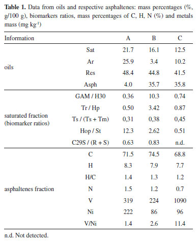
Semi-quantitative data were obtained for O and S by energy dispersive spectroscopy (EDS), relatively to atomic percentages, as it can be seen in Table 1S of the supplementary file. Then, the O atomic percentage was higher in samples B and C, possibly due to the biodegradation effect, whereas the S percentage increased in the supposedly "marine" sample C. Regarding the asphaltenes images obtained by ESEM (Figure 1S, supplementary file), regular and nonporous structures could be observed, without resin adsorption, indicating that these fractions were successfully purified. Additionally, V and Ni are generally associated with porphyrin nuclei, which are biomarkers related to origin and depositional environment, that concentrate in apshaltenes.41-43 V and Ni were determined in the asphaltenes fractions, and resulted in high concentrations and V/Ni >1, suggesting anoxic conditions. It can be seen from Table 1 that the asphaltenes from oil C showed a distinct and high Ni/V ratio, which can be related to the information about its marine origin. In the present study, all the alkanes (m/z 85) and biomarkers (m/z 191, 217) profiles were altered, due to the high degree of biodegradation of the samples, as it can be seen from the chromatograms in Figure 2. In particular, unresolved complex mixtures are present at m/z 85 and no homologous series of linear alkanes is observed. However, most of the hopanes and steranes were present in sample A, suggesting that this sample is less biodegraded.
 Figure 2. Linear alkanes (m/z 85), terpanes (m/z 191) and steranes (m/z 217) fragmentograms of the saturated fractions from oil samples A, B and C
As a consequence of the severe biodegradation, only few parameters were reliable, and these are presented in Table 1. The ratios of gammacerane relative to C30 hopanes (GAM/H30) and of tricyclic terpanes relative to hopanes (Tr/Hp) were distinctively higher in sample B. Since gammacerane is one of the most resistant compounds to secondary alteration processes, and its relative abundance increase through the degradation of other hopanes,44 then it is a clear indication of the higher biodegradation degree of this sample. Additionally, norhopanes have been cited as products of the demethylation process of regular hopanes during biodegradation in reservoir.45 In the case of our samples, 25-norhopane (25-NH) was identified only in sample B, which reinforced the indication of its higher level of biodegradation, in comparison to A and C. On the other hand, the steranes distribution, as seen from their altered chromatograms (Figure 2, m/z 217) limited the discussion to the biodegradation effect. In fact, the C27-C29 steranes, which are less resistant to biodegradation, were present in sample A, which suggested a lower effect of biodegradation on this sample. By analysing the steranes series, the susceptibility of biodegradation is ααα 20R > αbβ 20R > αbβ 20S > ααα 20S, which increases the parameter C29S/(R + S) according to the level of biodegradation, which was higher in the sample B, as discussed. The ratio of hopanes/steranes (Hop/St) can also provide information about depositional environment. In this case, the sample C value which was less than 4, is in agreement with a marine origin, whereas sample A showed a value higher than 7, in agreement with a lacustrine one. However, the parameter value for sample B did not corroborate the supposed lacustrine origin, the reason being possibly the high level of biodegradation which affected this oil. In addition, similar values for the ratio of trisnorhopanes Ts/(Ts + Tm) were obtained for A and B samples, which corroborated their common and supposedly lacustrine origin. Of course, more samples would be necessary in order to verify the overall source effect. Structural analyses of the asphaltenes The FTIR and 1H NMR techniques were used in an exploratory investigation, to access general aspects of the asphaltenes structure, regarding the sample biodegradation. FTIR was used to identify functional groups while 1H NMR was used to determine the chemical structure, so that the results were discussed below. Possible related functional groups were observed from the FTIR profiles (Figure 3) and listed in Table 2. Consequently, samples A, B, and C asphaltenes were at first classified by the occurrence of polar groups. The broad O-H and N-H stretching band at 3345 cm-1, was only present in samples B and C asphaltenes. Then, the presence of carboxylic acids in these samples was confirmed by the aromatic C=O stretching at 1700 cm-1, which was not present in the sample A asphaltenes (Figure 3). Carboxylic acids are generated under aerobic and anaerobic conditions from the partial oxidation of hydrocarbons. Consequently, in the present case, carboxylic acids could be inferred as by-products from biodegradation on asphaltenes of the two samples. As well, phenols, amides and aromatic amine groups may be present in B and C asphaltenes, and bands relative to the C-O stretching (1100 cm -1 to 1150 cm -1) suggested the presence of alcohols and esters. Additionally, the bands around 1030 cm-1 were common for all three asphaltenes and related to C-O stretching or S=O stretching displaced by conjugation.
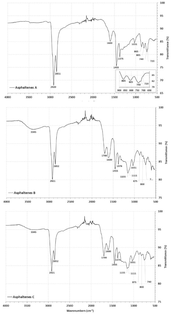 Figure 3. Infrared spectra (FTIR) of A, B and C asphaltenes
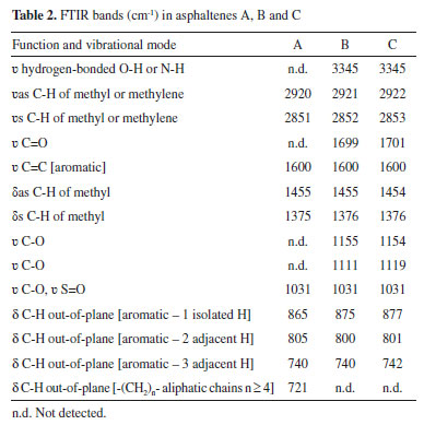
From Figure 3, all three asphaltenes showed bands at 2922 cm-1 to 2851 cm-1 of asymmetric and symmetric stretching of methyl and methylene.46 In the case of vibrational bands relative to aromatic rings, three bands were observed, corresponding to the C-H out-of-plane vibrations with only one hydrogen substituent (865 cm-1 to 875 cm-1) two (800 cm-1) and three adjacent hydrogens (740 cm-1), present in all asphaltenes FTIR spectra. The profile of these bands was different for sample A asphaltenes, in comparison to B and C. In the region between 900 cm-1 and 700 cm-1, there is a large overlap of bands, so that other arrangements of mono-substituted, di-substituted, and tri-substituted rings may be present. Also, the asphaltenes of sample A presented the characteristic band at 720 cm-1 from C-H out-of-plane deformation of longer alkyl substituents. The 1H NMR analysis provided qualitative and quantitative information on the hydrogens present in the asphaltenes. The hydrogen content coupled in saturated bonds or aromatic rings in different positions supported the discussion concerning the structure of samples A, B, and C asphaltenes. The obtained spectra were integrated and normalized by the total signal located in the region of 0-1 ppm, as seen in Figure 2S of the supplementary file. The areas related to saturated and aromatic hydrogens correspond to the % molar content of the respective types of hydrogen present in the analyzed asphaltenes. The relative concentration that was obtained is shown in Table 3, and the types of hydrogen are illustrated in Figure 2S. In particular, the di aromatic or higher hydrogens (Hdar) were more abundant than monoaromatic (Hmar), suggesting that the aromatic structures are mostly polycondensated rings. To compare the size of aliphatic substitutions between the asphaltenes, the average carbon number per alkyl substitution, shown in Table 3, was calculated from the integrated areas using the Dickinson equation:47 
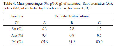
Asphaltenes A has the lowest H content in di-aromatic or larger rings. Lower Hγ content can also be observed, which indicates lower % CH3, which may suggest the presence of larger paraffin chains. This finding is in agreement with the C, H, and N mass percentages and infrared analysis of the asphaltenes in sample A that show absorption bands of long aliphatic chains. Asphaltenes B, in contrast, has higher % CH3 (Hγ) content and therefore smaller chains. The value of n in asphaltene B is clearly higher than the values of n in asphaltenes A and C. A higher Hβ content and lower Hα content of asphaltenes B along with having lower chains may be indicating structures with a more condensed core formed by aromatic and naphthenic rings. Asphaltenes C have higher total aromatic H content (Har) and also higher H content in di- or higher aromatic rings (Hdar). Occluded hydrocarbons obtained from asphaltenes The capacity of asphaltenes to incorporate hydrocarbons in their structures has been cited as an important advantage regarding biodegradation, since the occluded hydrocarbons would be preserved.35 The presence of these occluded compounds has a direct impact on the evaluation of oil for refining and on the generation of oil during cracking processes.48 After the oxidative treatment of the asphaltenes separated from the three heavily biodegraded oils, the resulting masses of occluded hydrocarbons were fractionated into saturated, aromatics and polars (Figure 1). The overall quantities were low, thus they were insufficient for biomarker analyses. As it can be seen from Table 4, asphaltenes A generated a higher percentage of occluded saturated and aromatics hydrocarbons. On the contrary, samples B and C asphaltenes showed similar percentages, with higher % polars in comparison to A.
The abundance of occluded hydrocarbons in the samples A, B, and C asphaltenes were also evaluated using the m/z 85 extract ion chromatogram of the saturated fractions (Figure 4). A homologous series of linear alkanes were observed in the occluded fractions, which is different from the saturated fractions of the maltenes obtained from the oils (Figure 2, m/z 85). However, the distribution profiles showed a possible biodegradation effect on occluded hydrocarbons, with a predominance of C24-C30 alkanes, while C14-C23 alkanes were less abundant. Besides, the presence of light hydrocarbons (C10 to C14) in the case of sample A is not clear, and could be derived from the less condensed and longer aliphatic chains observed from its structural analysis (see more in "structural analyses of the asphaltenes" topic). Moreover, a clear similarity in the occluded linear alkanes was observed for samples B and C (Figure 4, m/z 85), which is in agreement with the similarities found for the structures of their asphaltenes. The occluded mixture of even-carbon-numbered compounds seen in the m/z 69 extract ion chromatogram (Figure 4), was attributed to the n-alk-1-enes (< n-C22)49,50 that are present in the more biodegraded samples B and C, again with similar profiles. These results indicate that, in the case of heavily biodegraded oils, it is likely that the occluded compounds are no longer protected from biodegradation. Of course, this is a first general observation from the overall data, and it should be corroborated with further experiments.
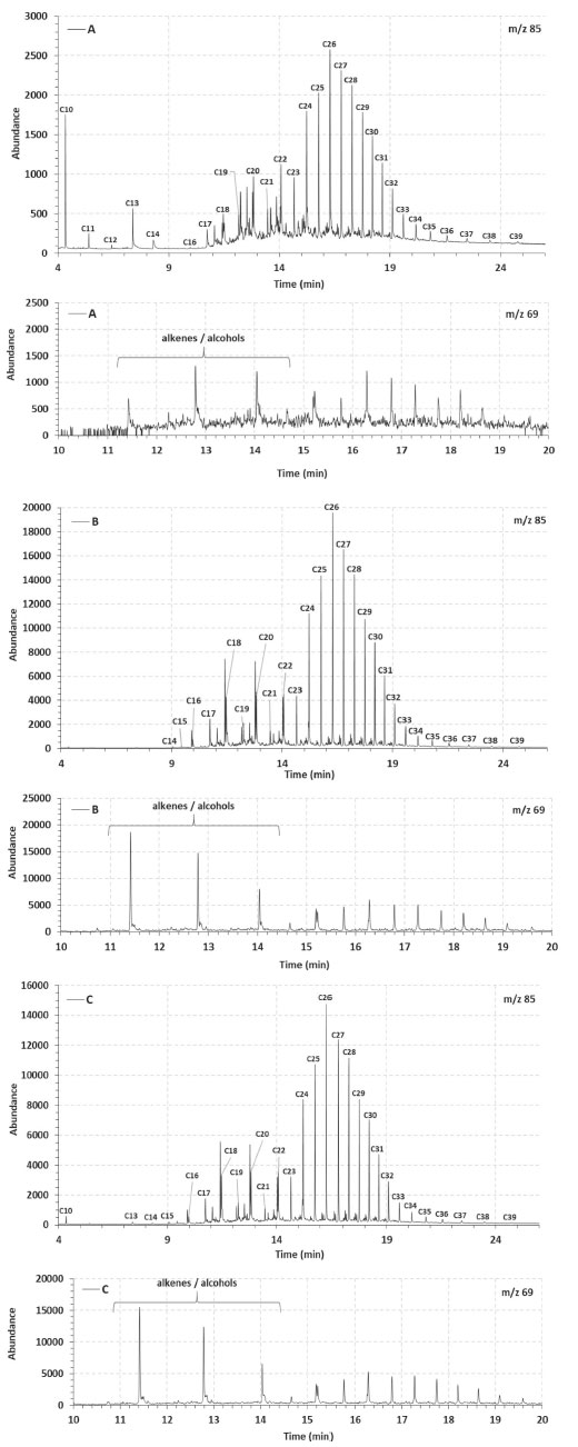 Figure 4. Linear alkanes (m/z 85) and m/z 69 fragmentograms of the occluded saturated fraction separated from asphaltenes A, B and C
CONCLUSIONS The asphaltenes from three Brazilian heavily biodegraded oils were successfully separated and investigated regarding biodegradation effects. The elemental analysis of these fractions were discussed together with the oils biomarker profiles, and indicated an increased effect of biodegradation in the following order A > C > B. Besides, biomarkers parameters and Ni/V ratio supported a lacustrine origin for A and B, and a marine one for C, however biodegradation masked source effects. FTIR and 1H RMN data of the asphaltenes were integrated, in order to observe biodegradation effects on their structure. Then, similar polar groups such as carboxylic acids were detected in the asphaltenes B and C, whereas asphaltenes A showed longer aliphatic chain substituents. Also, the degree of condensation of the aromatic rings followed the biodegradation order of the samples. The similarities in the asphaltenes B and C were also observed in their occluded hydrocarbon profiles (m/z 85 and 69). The asphaltenes from sample A resulted in more preserved occluded hydrocarbons. The results of this exploratory investigation suggested that severe biodegradation has an overall and similar effect on the structures of asphaltenes. Moreover, the quantity and quality of the occluded hydrocarbons were also found to be affected. The integration of the techniques used in this study was highly relevant for extracting information about the asphaltenes fractions composition of heavily biodegraded oils, and should be further explored.
SUPPLEMENTARY MATERIAL Scanning Electron Microscopy images, Energy Dispersive Spectroscopy data and H1-NMR data for asphaltenes A, B and C are available at http://quimicanova.sbq. org.br in the form of a PDF file, with free access.
ACKNOWLEDGEMENTS The authors thank the National Research Council of Brazil (CNPq) for the grants, and the Research and Development Center of Petrobras (CENPES) and Petroleum National Agency (ANP) for all financial support. Special thanks to D. J. Miller, S. M. C. de Menezes and L. S. Chinelatto Jr from CENPES, for their valuable contribution.
REFERENCES 1. EPE; Boletim de Conjuntura da Indústria de Petróleo 2019 - número 06; Rio de Janeiro, 2019, available at https://www.epe.gov.br/sites-pt/publicacoes-dadosabertos/publicacoes/PublicacoesArquivos/publicacao-226/topico471/Boletim%20de%20Conjuntura%20da%20Indu%CC%81stria%20do%20Pe tro%CC%81leo_1S19_2019_07_04_final.pdf, accessed December 2020. 2. Haggerty, J. H.; Kroepsch, A. C.; Walsh, K. B.; Smith, K. K.; Bowen, D. W.; The Extractive Industries and Society 2018, 5, 619. 3. Santos, I. C.; Hildenbrand, Z. L.; Schug. K. A.; Anal. Chem. 2019, 91, 689. 4. Oh, K.; Ring, T. A.; Deo, M. D.; J. Colloid Interface Sci. 2004, 271, 212. 5. Rogel, E.; Ovalles, C.; Moir, M.; Energy Fuels 2010, 24, 4369. 6. Forte, E.; Taylor, S. E.; Adv. Colloid Interface Sci. 2015, 217, 1. 7. Daaou, M.; Larbi, A.; Martínez-Haya, B.; Rogalski, M. A.; J. Petrol. Sci. Eng. 2016, 138, 50. 8. Ferreira, S. R.; Barreira, F. R.; Spinelli, L. S.; Leal, K. Z.; Seidl, P.; Lucas, E. F.; Quim. Nova 2016, 39, 26. 9. Alcázar-Vara, L. A.; Zamudio-Rivera, L. S.; Buenrostro-González, E.; J. Dispersion Sci. Technol. 2016, 37, 1544. 10. Luo, P.; Wang, X.; Gu, Y.; Fluid Phase Equilib. 2010, 291, 103. 11. Sabbah, H.; Morrow, A. L.; Pomerantz, A. E.; Zare, R. N.; Energy Fuels 2011, 25, 1597. 12. Mullins, O. C.; Sabbah, H.; Eyssautier, J.; Pomerantz, A. E.; Barré, L.; Andrews, A. B.; Ruiz-Morales, Y.; Mostowfi, F.; Mcfarlane, R.; Goual, L.; Lepkowicz, R.; Cooper, T.; Orbulescu, J.; Leblanc, R. M.; Edwards, J.; Zare, R. N.; Energy Fuels 2012, 26, 3986. 13. Duyck, C.; Miekeley, N.; Silveira, C. L. P.; Szatmari, P.; Spectrochim. Acta, Part B 2002, 57, 1979. 14. Duyck, C.; Miekeley, N.; Silveira, C. L. P.; Aucélio, R.; Campos, R. C.; Grinberg, P.; Brandão, G. P.; Spectrochim. Acta, Part B 2007, 62, 939. 15. Gabrienko, A. A.; Morozov, E. V.; Subramani, V.; Martyanov, O. N.; Kazarian, S. O.; J. Phys. Chem. C. 2015, 119, 2646. 16. Riley, B. J.; Lennard, C.; Fuller, S.; Spikmans, V.; Forensic Sci. Int. 2016, 266, 555. 17. Rakhmatullin, I. Z.; Efimov, S. V.; Tyurin, V. A.; Al-Muntaser, A. A.; Klimovitskii, A. E.; Varfolomeev, M. A.; Klochkov, V. V.; J. Petrol. Sci. Eng. 2018, 168, 256. 18. Lisitza, N. V.; Freed, D. E.; Sen,P. N.; Song, Y.; Energy Fuels 2009, 23, 1189. 19. AlHumaidan, F. S.; Hauser, A.; Rana, M. S.; Lababidi, H. M. S.; Energy Fuels 2017, 31, 3812. 20. Snowdon, L. R.; Volkman, J. K.; Zhang, Z.; Tao, G.; Liu, P.; Org. Geochem. 2016, 91, 3. 21. Chacón-Patino, M. L.; Vesga-Martínez, S. J.; Blanco-Tirado, C.; Orrego-Ruiz, J. A.; Gómez-Escudero, A.; Combariza, M. Y.; Energy Fuels 2016, 30, 4550. 22. Kashirtsev, V. A.; Russian Geology and Geophysics 2018, 59, 975. 23. Spigolon, A. L. D.; Fontes, R. A.; Binotto, R.; da Silva, T. F.; Cerqueira, J. R.; Garcia, D. F. In Asphaltenes: Fundamentals, Applications and Future Developments; Pittman, S. R., ed.; Nova Science Pub Inc: United Kingdom, 2016, chapter 3. 24. Rubinstein, I.; Spyckerelle, C.; Strausz, O. P.; Geochim. Cosmochim. Acta 1979, 43, 1. 25. Behar, F.; Pelet, R.; J. Anal. Appl. Pyrolysis. 1984, 7, 121. 26. Magnier, C.; Huc, A. Y.; Org. Geochem. 1995, 23, 963. 27. Liao, Y. H.; Zheng, Y. J.; Pan, Y. H.; Sun, Y. G.; Geng, A. S.; Org. Geochem. 2015, 79, 49. 28. Pan, Y. H.; Liao, Y. H.; Zheng, Y. J.; Org. Geochem. 2015, 86, 32. 29. Ekweozor, C. M.; Org. Geochem. 1984, 6, 51. 30. Ekweozor, C. M.; Org. Geochem. 1986, 10, 1053. 31. Peng, P. A.; Morales-Izquierdo, A.; Hogg, A.; Strausz, O. P.; Energy Fuels 1997, 11, 1171. 32. Liao, Z.; Graciaa, A.; Geng, A.; Chrostowska, A.; Creux, P.; Appl. Geochem. 2006, 21, 833. 33. Liao, Z.; Geng, A.; Graciaa, A.; Creux, P.; Chrostowska, A.; Zhang, Y.; Org. Geochem. 2006, 37, 291. 34. Azevedo, D. A.; Silva, T. F.; Silva, D. B.; Quim. Nova 2009, 32, 1770. 35. Zhao, J.; Liao, Z.; Zhang, L.; Creux, P.; Yang, C.; Chrostowska, A.; Zhang, H.; Graciaa, A.; Appl. Geochem. 2010, 25, 1330. 36. Cheng, B.; Yang, C.; Du, J.; Zhao, J.; Liao, Z.; Mar. Pet. Geol. 2014, 51, 49. 37. Liao, Z.; Geng, A.; Org. Geochem. 2002, 33, 1477. 38. Souza, J. R.; Duyck, C. B.; Fonseca, T. C. O.; Saint'Pierre, T. D.; J. Anal. At. Spectrom. 2012, 27, 1280. 39. Speight, J. G.; The Chemistry and Technology of Petroleum, 5th ed., CRC Press: Boca Raton, 2014. 40. Rocha, Y. dos S.; Pereira, R. C. L.; Filho, J. G. M.; Org. Geochem. 2018, 124, 29. 41. Callot, H. J.; Ocampo, R.; Albrecht, P.; Energy Fuels 1990, 4, 635. 42. Escobar, M.; Márquez, G.; Azuaje, V.; Da Silva, A.; Tocco, R.; Fuel 2012, 97, 186. 43. Galarraga, F.; Reategui, K.; Martïnez, A.; Martínez, M.; Llamas, J. F.; Márquez, G.; J. Petr. Sci. Eng. 2008, 61, 9. 44. Huang, H.; Biodegradation. 2017, 28, 313. 45. Li, N.; Huang, H.; Jiang, W.; Wuc, T.; Sun, J.; Org. Geochem. 2015, 78, 33. 46. Asemani, M.; Rabbani, A. R.; J. Petr. Sci. Eng. 2020, 185, 1. 47. Dickinson, E. M.; Fuel 1980, 59, 290. 48. Peters, K. E.; Walters, C. C.; Moldowan, J. M.; The biomarker guide: Biomarkers and Isotopes in the Petroleum Exploration on Earth History, 2nd ed., Cambridge University Press: United Kington, 2005. 49. Van Bree, L. G. J.; Rijpstra, W. I. C.; Cocquyt, C.; Al-Dhabi, N. A.; Verschuren, D.; Sinninghe Damste, J. S.; de Leeuw, J. W.; Geochim. Cosmochim. Acta 2014, 145, 89. 50. Yang, C.; Liao, Z.; Zhang, L.; Creux, P.; Energy Fuels 2009, 23, 820. |
On-line version ISSN 1678-7064 Printed version ISSN 0100-4042
Qu�mica Nova
Publica��es da Sociedade Brasileira de Qu�mica
Caixa Postal: 26037
05513-970 S�o Paulo - SP
Tel/Fax: +55.11.3032.2299/+55.11.3814.3602
Free access


