Artigo
| Precision design of proton exchange membrane fuel cell flow field based on water and heat transfer mechanism |
|
Xiangrong LiaoI; Jianbin SuII; Chonlatee PhotongIII,* I. Fujian Polytechnic of Information Technology, Fujian, 350003 China Received: 10/24/2023 *e-mail: 13609517160@163.com The article establishes a three-dimensional multiphase proton exchange membrane single-cell model and investigates the impact of precision flow field design on the electrochemical characteristics, heat mass transfer properties, and phase change characteristics of fuel cells. The simulation model is analyzed using COMSOL 6.0 multiphysics software and validated using experimental data under the same operating conditions. The research results indicate that precision flow field design can enhance the electrochemical characteristics of proton exchange membrane fuel cells (PEMFC) by reducing concentration overpotentials through improved gas mass transfer, thus increasing the performance of cell. Precision flow field design improves gas and current density distribution uniformity, promoting more uniform electrochemical reactions and enhancing cell durability. Finally, precision flow field design increases gas mass transfer rates, effectively removing liquid water from the interior and facilitating smoother gas transport to the active regions. This study provides new insights into flow field design for fuel cells. INTRODUCTION Proton exchange membrane fuel cells (PEMFCs), with their high energy density, no air pollution, and high energy conversion efficiency, have emerged as one of the ideal power sources in the 21st century. However, the transient response characteristics of fuel cells remain a critical factor hindering their commercialization. Recognizing this, the academic community has employed various methods to enhance their performance, and flow field optimization is one of these methods.1-3 The flow field on the bipolar plates plays a crucial role in PEMFC operation. It evenly distributes the fuel and oxidant required for electrochemical reactions to ensure uniform current density distribution. It facilitates the smooth removal of reaction-generated water under the influence of exhaust gases and entrainment.4 The focus of flow field optimization design primarily revolves around flow field geometry and dimensions. Traditional flow field design: currently, commonly used flow field structures include traditional ones like parallel flow fields and serpentine flow fields, as well as newer designs such as 3D flow fields, biomimetic flow fields, and radial flow fields. In the case of parallel flow fields, gas experiences low flow resistance when flowing through it. However, these flow fields need better water management characteristics. Water vapor generated during electrochemical reactions tends to condense within the channels, blocking the gas transport and resulting in uneven distribution of reaction gases in the electrocatalytic region. To address these issues, researchers have made various attempts.5-7 Timurkutluk and Chowdhury8 investigated the impact of variable cross-sectional structures with width and height gradually narrowing along the length on straight flow fields. The results confirmed that such variable cross-sectional structures can effectively improve the distribution of oxygen and water on the cathode catalyst layer. Serpentine flow field structure is a structure widely used in recent years. It is a continuous channel of reciprocating and bending from the inlet to the outlet. Compared with the parallel flow field, the serpentine flow field has better water removal performance, and it is not easy to appear flooding in the flow field. However, because the serpentine flow field has many inflection points that can change the gas flow direction sharply, the flow field easily produces a large pressure drop, resulting in an insufficient reaction gas supply in the second half of the flow field. Some experts9,10 proposed multiple snake flow fields to solve the problem of excessive pressure drop in the snake flow field. The simulation analysis shows that the PEMFC performance can be improved by adjusting multiple serpentine flow fields' number, size, and length. New flow field design: based on the traditional flow field, some researchers proposed a new flow field, such as a 3D flow field, bionic flow field, and radial flow field, and conducted simulation research. Toyota proposed the 3D flow field and has now achieved mass production on its hydrogen cell model Mirai. The structural characteristic of a 3D flow field is that many microflow fields are processed based on the structure of the straight flow field on the cathode side. The air spreads through the microcurrent field and can flow more fully to the catalyst layer to participate in the reaction. At the same time, the product water can also be quickly removed from the flow field through the microcurrent field to avoid the problem of water aggregation and blocking the flow field. Niu et al.11 designed two new 3D flow fields of cathode flow field by increasing the baffle at the surface to improve the gas diffusion layer and enhance the mass transfer between the flow field and the gas diffusion layer. Zhang et al.12 established a three-dimensional multiphase numerical model of PEMFC and studied PEMFC with a 3D fine pore flow field. They found that a 3D thin pore flow field can significantly improve the reactive gas supply from the flow field to the porous electrode and simultaneously promote the removal of liquid water in PEMFC. The biomimetic flow field draws on biological structures such as leaf veins and animal lungs, and the advantages of such structures in mass transfer and heat transfer have been verified in relevant literature.13,14 Kang et al.15 studied the gas transmission phenomenon of the wing vein flow field. Compared with the serpentine flow field and the leaf vein flow field, the wing vein flow field can significantly improve the uniformity of the reaction gas concentration distribution in the gas diffusion layer (GDL), which is more conducive to strengthening the mass transfer of the reaction gas. Damian-Ascencio et al.16 studied the role of mass transfer reinforcement of tree-like flow field structure in the design of the introduced cross-flow field. The results show that introducing a tree-type flow field can better reduce the water content in the proton exchange membrane and improve water transmission performance. The radial flow field structure adopts the central intake arrangement, and the gas flows from the inlet at the center of the flow field to the periphery of the flow field and finally exits the PEMFC through the outlet distributed at the edge of the circular bipolar plate. Compared with the two new flow fields above, the radial flow field has the advantages of a short intake path, easy processing, and convenient stacking under the same working area. Cano-Andrade17 selected a quarter of the radial flow field region and simulated the current density distribution characteristics of PEMFC and the mass transfer characteristics of GDL with the structure of 4, 8, and 12 flow fields. The results show that the three factors significantly improve performance than the traditional parallel and snake flow fields. Optimized design of the flow field size: after many experiments and simulation studies, many researchers18,19 believe that the length of the flow field greatly impacts cell performance. These effects are mainly manifested in the fact that the longer the flow field, the greater the pressure loss, the lower the gas concentration of the reaction in the later stage, and the flooding phenomenon, thus reducing the cell performance. There is little research on the impact of flow field depth on cell performance, but many designers believe that a shallow flow field can get a significant flow rate and prevent flooding to get a better performance.20,21 There are many studies22,23 on the influence of flow field width on PEMFC performance, and many experimental and simulation results show that a small ridge width and a large flow field width can promote the reaction gas mass transfer, thus improving cell performance. Most researchers24-28 are studying the section shape problem from the perspective of pressure drop loss and processing methods. For example, the triangular and semicircular section is more conducive to reducing the pressure drop than the rectangular section; the increase of the slope angle will cause the increase of the maximum power density and current density of PEMFC, and the trapezoidal section flow field can effectively remove liquid water and so on. Some scholars29 believe that changing the internal structure of the flow field, such as adding a baffle inside the flow field, can effectively improve the quality transfer performance of PEMFC. In conclusion, the following problems exist in the flow field optimization design: (i) there are many studies on the flow field form and the optimization design of the flow field structure size. The new flow field design is constantly proposed, and the relationship between the flow field size and PEMFC performance is relatively clear. However, there are few studies on more precise, small-size flow field design; (ii) to study the optimal design of the flow field, the evaluation indexes are often external characterization, such as current density and power density, as well as internal characteristics, such as gas and electric density distribution. The influence of the change of the flow field on the mass transfer and water vapor phase transition inside the cell is ignored. Given this, this paper proposes a flow field precision design strategy to compare and analyze the influence of flow field forms with different size accuracy, such as width × height: 1 mm × 1 mm, 0.7 mm × 0.7mm, and 0.5 mm × 0.5 mm, on PEMFC performance. The influence of the precision design of the exploration field on the water heat transfer and water vapor phase transition law of the fuel cell provides a new idea for the flow field design of the fuel cell flow field.
EXPERIMENTAL Methodology Mathematical equations Fuel cell internal includes electrochemical reaction, phase change, mass transfer, heat transfer, and other complex processes. Therefore, in the simulation calculation, it is necessary to use multiple mathematical equations to make the calculation more accurate. The main mathematical equation contains the following categories. Electrochemical equations The electrochemical equations reveal the crucial electrochemical reactions occurring in fuel cells. Typical fuel cell reactions involve the electrochemical oxidation-reduction processes of hydrogen and oxygen at the anode and cathode, respectively. These equations provide the foundation for understanding the energy conversion mechanisms within fuel cells. The equations are as follows: (i) Exchange current density  where i0,a is the anodic exchange current density; is the anode reference exchange current density; sl is the saturation of liquid water; sice is the saturation of ice; is the hydrogen concentration; is the hydrogen reference concentration; T is the cell temperature.  (ii) Open circuit voltage  where Vout is the output voltage; Vnernst is the Nister voltage; ηact,a is the anodic activation of the overpotential; ηact,c is the cathodic activation by overpotential; ηconc,a is the anode concentration difference and overpotential; ηconc,c is the cathodic concentration overpotential; ηohmic is the ohm overpotential. (iii) Nernst voltage  where pH2 is the hydrogen pressure; pO2 is the oxygen partial pressure. (iv) Activated over-potential 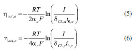 where αa and αc is the transfer coefficient of the anode and the cathode; I is current density; δCL is catalytic layer (CL) thickness. (v) 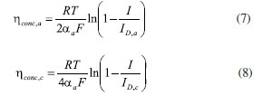 where ID,a and ID,c are the limiting current density of the anode and the cathode, respectively. (vi) Limiting current density 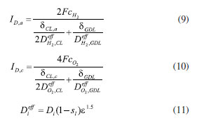 where δGDL is GDL thickness; Deff is the reference diffusion coefficient; ε is porosity. (vii) Coefficient of diffusion 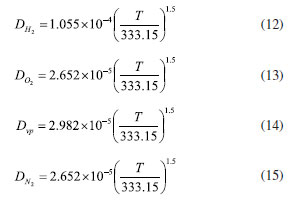 (viii) Ohm overpotential  where δMEM is the thickness of the membrane; σs,GDL, σs,CL, σs,MEM are the electrical conductivity of the GDL, CL and membrane. Conservation equations In fuel cells, the conservation equations for energy, mass, and charge describe the transfer and conversion of these quantities within the system. These equations are crucial for understanding the operational principles of fuel cells and for optimizing their design and performance. Here are some important conservation equations in fuel cells and their roles: (i) Mass conservation  where ρg is the gas mixing density; Sm is the quality source phase; Y is the mole fraction; M is the relative molecular weight. (ii) Momentum conservation 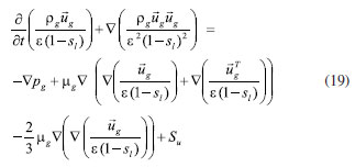 where Su is the momentum source phase. (iii) Material conservation (hydrogen gas, oxygen, and water vapor) 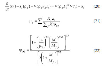 where µg is the ideal mixed gas dynamic viscosity; X is the mole fraction; µi is the dynamic viscosity of the gas; ψ is the relative molar mass; Dieff is the gas reference diffusivity factor; Si is the material source phase. (iv) Gas power viscosity 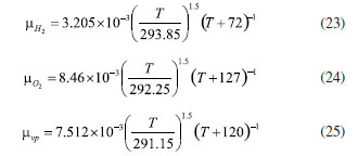 (v) Liquid water conservation 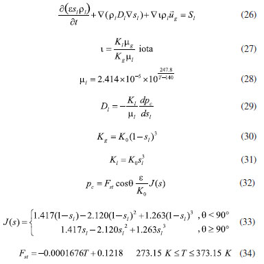 where ρl is the density of water; µl is the liquid hydrodynamic viscosity; ι is the interface resistance coefficient; Dl is the liquid-water diffusion coefficient; pc is the capillary pressure; Fst is the surface tension between liquid water and gas; K0 is the permeability; θ is the contact angle; Kl is the effective liquid permeability; Kg is the relative gas-phase permeability. (vi) Ionomer hydration water conservation 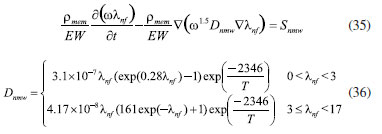 where ρmem is the dissociation polymer density; EW is the isomeric equivalents; ω is the volume fraction of the ionomers in the CL; Dnmw is the ionomer hydration water diffusion coefficient; λnf is the ionomer hydration water content. (vii) Charge conservation 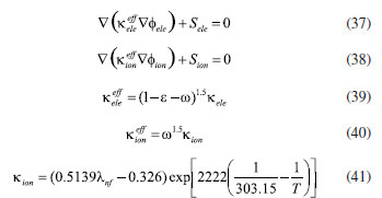 where κion is the ionic conductivity; κele is the electron conductivity; is the reference ion conductivity; is the reference to the electron conductivity. (viii) Energy conservation 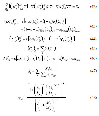 where ρsld is the solid phase density (solid phase excluding membrane electrolytes and ice); (Cp)sld is the effective volume heat capacity (solid phase excluding membrane electrolytes); is the effective volume heat capacity (solid phase including membrane electrolytes); is the effective volume heat capacity (liquid phase); (Cp)g is the specific heat capacity of the mixed gas; (Cp)l is the liquid water specific heat; (Cp)ice is the ice specific heat; (Cp)mem is the ionomer specific heat; (Cp)sld is the solid phase (not include the membrane electrolytes and the ice) specific heat; is the effective thermal conductivity; kl is the thermal conductivity of the liquid water; kg is the thermal conductivity of the mixed gas; ksld is the solid phase does not include the membrane electrolyte thermal conductivity; kmem is the thermal conductivity of the ionomers. Equations of phase change In the actual work of the fuel cell, the mutual phase transition between liquid water, water vapor, and ionomer hydration water is involved. Generally, it is expressed by the following equations: (i) Water vapor-liquid water 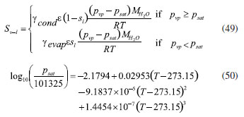 where Sv–l is the steam-liquid water source item; γevap is the condensing rate; γcond is the condensing rate. (ii) Ionomer hydration water-water vapor 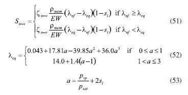 where Sn–v is the ionomer hydration water-water vapor source term; ζn–v is the ionomer hydration water-water vapor conversion rate; ζv–n is the water vapor-ionomer hydration water conversion rate; psat is the saturated vapor pressure. Source phase The individual source phases in the formula are calculated by the following equations: (i) Material source item 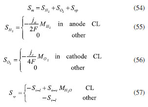 (ii) Momentum source term  (iii) Liquid water source item  (iv) Ionomer hydration water source item 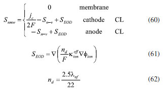 where nd is the electro-seepage drag coefficient; SEOD is the drag source phase. (v) Electronic source item  where ja is the anodic volume-exchange current density; jc is the cathodic volume-exchange current density. (vi) Proton source term 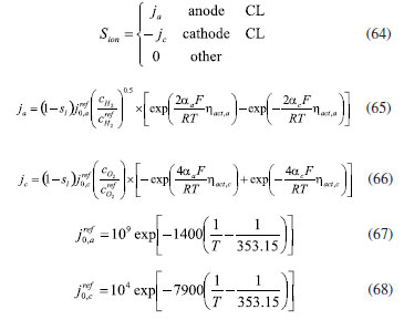 where is the anode volume reference exchange current density; is the cathodic volume reference exchange current density. (vii) Energy source term 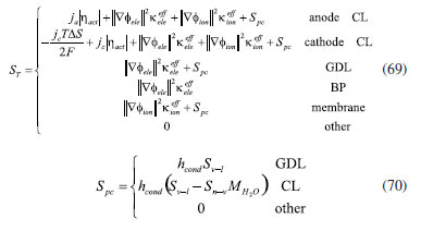 where ηact is the overpotential; Spc is the latent heat function; hcond is the latent heat of condensation. Computational domain The model in this paper is a single cell with a 3 cm × 3 cm flow field. The calculation area includes the proton exchange membrane, cathode catalytic layer (CL), anode CL, cathode GDL, anode GDL, cathode flow field, and anode flow field. The original flow field dimension is width × height = 1 mm × 1 mm (Figure 1a). The precision dimensions are 0.7 mm × 0.7 mm (Figure 1b) and 0.5 mm × 0.5 mm (Figure 1c). In addition, the mechanism of water and heat transfer within the internal cross-section of the flow field is also discussed in detail, and the cross-section is shown in Figure 1d.
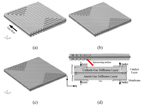 Figure 1. The calculated area
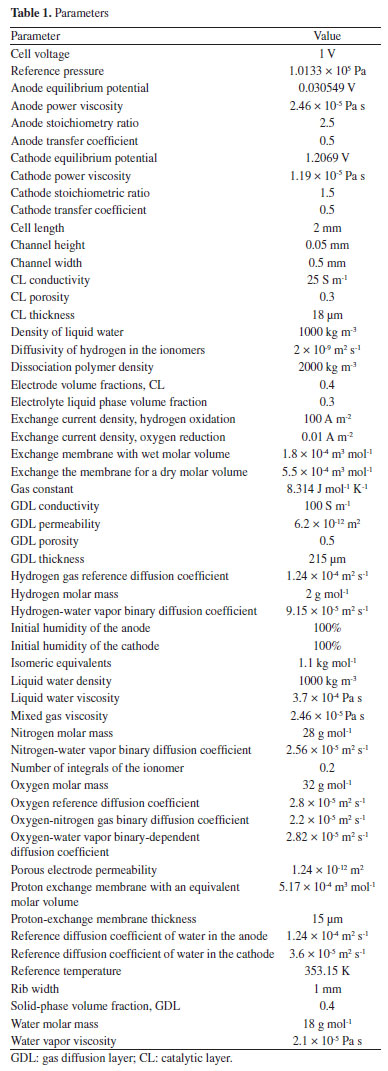
Model hypothesis (i) The fuel cell reaction process is a constant temperature process; (ii) Flow is laminar, an incompressible flow; (iii) The gravity effect is ignored; (vi) Porous media, such as GDL and CL, are all isotropic; (v) GDL and CL are hydrophobic, and their contact angle is greater than 90º; (vi) When the liquid water crosses the junction of the GDL, the gas carries the flow field, that is, liquid water only exists in GDL and CL. Basic parameters In this paper, the simulation model was built by the COMSOL Multiphysics 6.0, and the parameters of the model are shown in Table 1.
Boundary condition Before the conserved equation could be solved, the boundary conditions and the initial values must be set. For the flow boundaries, the entrance mass flow rate is determined by the respective current density, gas stoichiometry, and active reaction area. The total cathode-molar mass:  The total anode-molar mass:  The cathode mass flow rate:  The anode molar flow:  where xO2,in is the inlet mole fraction of oxygen; xH2Oc,in is the inlet mole fraction of cathode water vapor; xN2,in is the inlet mole fraction of nitrogen gas; Mw,O2 is the molar masses of oxygen; Mw,H2O is the molar mass of water; Mw,N2 is the molar mass of nitrogen; xH2,in is the inlet molar fraction of hydrogen; xH2Oc,in is the inlet molar fraction of anode water vapor; stoichc is the cathode stoichiometric ratio; i is the current density; Acl is the active reaction area; stoicha is the anode stoichiometry ratio. Furthermore, the inlet velocity was expressed in accordance with the channel inlet area and the calculated mass flow rate. For the charge conservation equation, the potential of the anode GDL contacting the bipolar plate was set as the reference voltage (0 V). At the interface of the cathode GDL and the bipolar plate, the potential was defined as the cell operating voltage. Furthermore, the model used a constant temperature for all the calculated fields. For the remaining boundary conditions, no-flux or symmetry conditions were used as follows:  where χ is the variable associated with the model solution. Model verification The experimental procedure in this study begins with the activation of the membrane electrode assembly (MEA), employing an intermittent activation approach with a duration of twelve hours each day for a total of four days. Following activation, the fuel cell performance testing is conducted by discharging the cell from 0.4 to 0.8 V in increments of 0.05 V. During testing, an assembly torque of 3.0 N m is applied to the proton exchange membrane fuel cell (PEMFC), and the experimental cell temperature is maintained at 70 ºC. Figure 2b shows the comparison diagram of the polarization curve simulated and experimental fitted under the same conditions and the same geometric parameters (the specific parameters are shown in Table 2) (the experimental setup diagram is shown in Figure 2a). Figure 2 shows that the simulated polarization curve is highly consistent with the experiment, hence the reliability of the simulation model used in this paper.
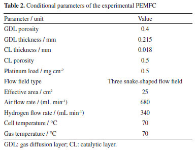
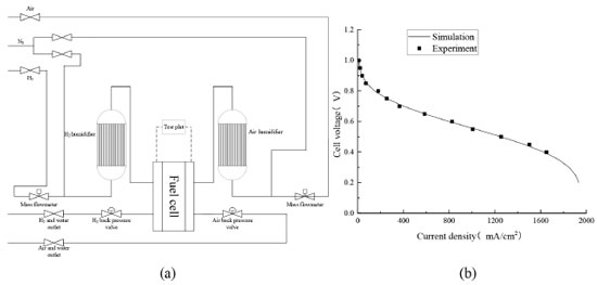 Figure 2. Test verification: (a) schematic diagram of experiment device; (b) comparison of experiment and simulation results
RESULTS AND DISCUSSION Electrochemical characteristics of different precision flow fields The polarization curve is a key tool to evaluate and optimize the performance of fuel cells. Generally, the polarization curve can be divided into three regions: the activated polarization region of low current density, the ohmic polarization region of medium current density, and the concentration polarization region of high current density. The above three regions represent the electrochemical reaction characteristics, ohm impedance characteristics, and mass transfer characteristics of the fuel cell, respectively. As can be seen in Figure 3, the activation polarization of the three precision flow fields is almost the same because the flow field precision design presented in this paper does not change the catalytic efficiency of the catalyst required for the electrochemical reaction.
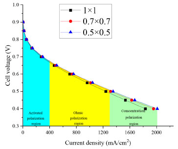 Figure 3. Comparison of PEMFC polarization curves of flow fields with different precision
With the improvement of flow precision (the smaller the flow size, the higher the precision), both ohm polarization and concentration polarization are reduced, and the improvement effect of concentration polarization is more obvious. The reduction of ohmic polarization shows that the precision design can effectively reduce the contact resistance between the flow channel and GDL and reduce the ohmic overpotential. The improvement of the concentration difference polarization effect shows that the precision design of the flow channel can improve the mass transfer performance and water removal characteristics, effectively improve the utilization rate of gas, and finally reduce the overpotential of the concentration difference. Concentration overpotential is a polarization phenomenon of fuel cells, which usually refers to the voltage loss on the electrode surface in the cell due to the difference in material concentration. The concentration difference overpotential mainly involves the transmission process of electrolyte, fuel, and oxygen inside the cell. Figure 4 shows the concentration overpotential of different precision flow fields. Obviously, with the increase of cell voltage, the concentration overpotential increases significantly. In addition, with the improvement of the cell precision degree, the concentration difference overpotential is significantly improved. As can be seen in this the figure, when the flow channel is refined from 1 mm × 1mm to 0.7 mm × 0.7 mm, the concentration difference overpotential at 0.4 V decreases from 0.3554 to 0.1033, a significant decrease. When the precision degree is further increased to 0.5 mm × 0.5 mm, the concentration difference overpotential at 0.4 V was further increased, but the improvement degree decreased.
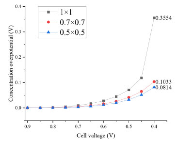 Figure 4. Concentration difference overpotential of different precision flow fields of PEMFC
The reason for the above phenomenon is that when the degree of precision is higher, the gas distribution of the flow channel is more uniform. As shown in Figure 1, with the improvement of precision, the number of channels increases, and the flow area through the GDL also increases. On the other hand, it can improve the gas distribution inside the GDL. The lower concentration difference overpotential can lift the higher material transmission and reaction rate of the fuel cell, which enables the cell to react under the condition of the lower voltage, thus improving the efficiency of the cell. Heat and water transfer characteristics of different precision flow fields Figure 5 shows the oxygen inhomogeneity Cv on the surface of PEMFC cathode GDL, which is usually used to represent the difference or imbalance between different parts. The calculation formula is:
 Figure 5. Analysis of oxygen inhomogeneity on the surface of cathode GDL of different precision flow field PEMFC
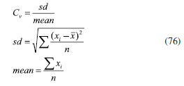 where sd is the standard deviation, mean is the average value. As can be seen in Figure 5, with the increase of the cell voltage, the Cv of the cathode GDL surface continuously increases, and the slope also gradually increases. The improvement of Cv indicates that oxygen distribution's inhomogeneity on the cathode GDL surface increases and greater inhomogeneity occurs in the low voltage area (high current density) area. Moreover, increasing flow channel precision improves the oxygen inhomogeneity on the cathode GDL surface. The above phenomenon is because oxygen diffusion on the cathode surface is limited at a high current density. The cell needs more oxygen when the current density increases to support the oxygen reduction reaction. However, the oxygen transfer rate in the gas channel or electrolyte may not meet this demand, resulting in a lower oxygen concentration near the flow outlet, thus causing an uneven distribution. Therefore, the precision design of the flow channel can improve the diffusion characteristics of oxygen in the GDL, thus reducing the inhomogeneity of oxygen. Figure 6 shows the molar fraction of oxygen on the surface of the PEMFC cathode GDL with different precision flow fields at the voltage of 0.4 V. Obviously, the oxygen distribution on the cathode GDL surface is more uniform with the increasing precision. Specifically, a significant region of low molar fraction of oxygen appeared at the GDL below the rib plate, especially in the 1 mm × 1 mm flow field PEMFC. This phenomenon is significantly improved with the improvement of flow field precision.
 Figure 6. Molar fraction of oxygen on the cathode GDL of PEMFC with different precision flow fields (cell voltage = 0.4 V): (a) 1 mm × 1 mm; (b) 0.7 mm × 0.7 mm; (c) 0.5 mm × 0.5 mm
The reason for the above phenomenon is that the precision design of the flow channel can reduce the flow resistance of the gas in the channel and the pressure drop. In addition, the increased number of flow channels with high precision PEMFC can reduce the gas flow speed difference within the flow channel and prevent the gas flow rate in some regions from being much higher than others. Eventually, the uniformity of the gas distribution is improved. Figure 7 shows the current density inhomogeneity of the PEMFC cathode CL surface with different precision. It can be seen that the current density inhomogeneity of the PEMFC cathode CL surface gradually decreases with the improvement of flow channel precision. The uneven distribution of current density will make the current density of some parts too high, leading to a low local electrochemical reaction rate, thus affecting the cell's overall performance. Moreover, too high a local current density will cause local hot spots, leading to the acceleration of electrochemical reactions in the high region and the aging of this region. In addition, long-term local hotspots can lead to perforation of the proton exchange membrane, ultimately causing cell damage. Therefore, the inhomogeneity of the current density distribution of PEMFC can be improved, thus improving the cell life.
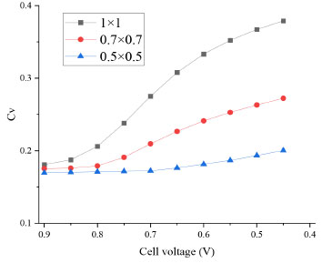 Figure 7. Current density inhomogeneity on the surface of the cathode CL of flow field
Figure 8 shows the surface current density distribution of PEMFC cathode CL at 0.4 V. It is obvious from the figure that the cathode CL surface current density distribution uniformity increases with increasing precision, and the maximum and minimum difference of current density of 1 mm × 1 mm, 0.7 mm × 0.7 mm, and 0.5 mm × 0.5 mm are 957, 724 and 558 mA cm2, respectively. The precision design can improve the current density's distribution uniformity. On the one hand, the uniformity of the gas distribution makes the gas reach the active area surface and makes the chemical reaction more uniform. On the other hand, the precision design of the flow field can improve the water removal performance of the flow channel, discharge the water produced by the reaction in time, and effectively prevent the local water flooding from hindering the mass transfer of the reaction gas.
 Figure 8. Current density distribution of PEMFC cathode CL surfaces with different precision flow fields (cell voltage = 0.4 V): (a) 1 mm × 1 mm; (b) 0.7 mm × 0.7 mm; (c) 0.5 mm × 0.5 mm
Figure 9 shows the air mass transfer velocity of PEMFC at 0.4 V (vertical direction). The figure shows positive and negative mass transfer velocity because both the intake and exhaust (the gas carries liquid water out) processes exist in the GDL. The mass transfer speed of air in GDL is significantly accelerated with the increasing precision of the flow field. The reason is that the precision design of the channel can reduce the spacing between the channels and reduce the path of gas diffusion, thus improving the mass transmission speed. In addition, when the inlet flow rate is certain, decreasing the inlet channel's surface area increases the gas's flow rate, thus increasing its mass transfer speed in the GDL.
 Figure 9. Mass transfer velocity of PEMFC with different precision flow fields (cell voltage = 0.4 V): (a) 1 mm × 1 mm; (b) 0.7 mm × 0.7 mm; (c) 0.5 mm × 0.5 mm
Analysis of PEMFC phase transition characteristics of different precision flow fields Within the normal operating temperature range of the fuel cell (60-80 ºC), there are three states of water: water vapor, liquid water, and ionomer hydration water. Under certain conditions, water transforms in the three states. For water vapor and liquid water, the phase transition between them is determined by the water vapor pressure and the saturated vapor pressure. According to Equations 49 and 50, when the water vapor pressure is greater than the saturated vapor pressure, the water vapor will change toward liquid water. On the contrary, if the water vapor pressure is less than the saturated vapor pressure, the liquid water will evaporate the phase change and then turn into water vapor. For ionomer hydration water and liquid water, the phase transition between them is influenced by the relationship between the equilibrium water content and the ionomer hydration water content. According to Equation 51, water vapor and ionomer hydration water are interconverted due to the relationship between equilibrium water content and ionomer hydration water content. This section will focus on the influence of the flow field precision design on the water phase transition in PEMFC. In fuel cells, liquid water is the main obstacle to gas mass transfer, especially in porous media; liquid water blocking the pore structure will cause a serious impact on the intake of air. Figure 10 shows the liquid water saturation of GDL in the adjacent flow field PEMFC. As can be seen in the figure, the saturation of liquid water inside GDL gradually decreases with the improvement of the flow precision. The reason is that, on the one hand, the flow field precision design can improve the mass transfer characteristics of the gas inside the porous medium, thus allowing the gas to take away more liquid water. On the other hand, the precision design of the flow channel can make the electrochemical reaction more sufficient, increase the consumption of oxygen, and reduce the pressure of oxygen, thus increasing the pressure of cathode water vapor and promoting the phase transition of liquid water to the direction of water vapor.
 Figure 10. Distribution of GDL liquid water in different precision flow field PEMFC (equal scale amplification, same size of MEA in the three figures): (a) 1 mm × 1 mm; (b) 0.7 mm × 0.7 mm; (c) 0.5 mm × 0.5 mm
Figure 11 shows the hydration water distribution of ionomer domains between the adjacent flow channels in PEMFC fields. Obviously, with the increase in flow field precision, hydration water gradually decreased. The reason is that with increasing flow field precision, the saturation of the liquid water inside the porous medium decreases. According to Equations 52 and 53, with the decrease of liquid water saturation, the water activity a decreases, thus reducing the equilibrium water content and promoting the phase transition from ionomer hydration water to water vapor. With the vapor phase transfer of ionomer hydration water, vapor pressure gradually increases. Finally, the removal of the liquid water is promoted under evaporation.
 Figure 11. Hydration water distribution of adjacent flow fields of the different precision flow field (equal scale amplification, same size of MEA in the three figures): (a) 1 mm × 1 mm; (b) 0.7 mm × 0.7 mm; (c) 0.5 mm × 0.5 mm
CONCLUSIONS This paper establishes a three-dimensional multiphase model to explore the influence of flow field precision design on the electrochemical characteristics, water and heat transfer characteristics, and fuel cell phase change characteristics. With the improvement of the flow field precision, the concentration difference overpotential is significantly improved, the gas utilization rate is improved, and the water removal performance of the flow field is increased. In this paper, the inhomogeneity (Cv) was used to measure the gas and current density distribution characteristics of different precision flow fields. With increasing precision, the oxygen distribution is more uniform, and the region of low molar fraction of oxygen is significantly reduced. Meanwhile, the current density distribution is more uniform, and the difference between maximum and minimum current density decreases. With the improvement of the flow field precision, the mass transfer speed of the gas is significantly improved, which increases the mass transfer characteristics of the gas and is conducive to removing liquid water. With the improvement of the flow field precision, the liquid water content inside GDL decreases, and the ionomer hydration water decreases, indicating that the flow field precision design can improve the water removal performance of the flow field.
REFERENCES 1. Yuan, H.; Dai, H.; Ming, P.; Zhao, L.; Tang, W.; Wei, X.; Chem. Eng. J. 2022, 431, 134035. [Crossref] 2. Tang, X.; Zhang, Y.; Xu, S.; Int. J. Heat Mass Transfer 2023, 206, 123966. [Crossref] 3. Shi, L.; Liu, P.; Zheng, M.; Xu, S.; Energy Convers. Manage. 2023, 278, 116725. [Crossref] 4. Cheng, C.; Yang, Z.; Liu, Z.; Tongsh, C.; Zhang, G.; Xie, B.; He, S.; Jiao, K.; Appl. Energy 2021, 302, 117555. [Crossref] 5. Khazaee, I.; Sabadbafan, H.; Heat Mass Transfer 2016, 52, 993. [Crossref] 6. Chowdhury, M. Z.; Genc, O.; Toros, S.; Int. J. Hydrogen Energy 2018, 43, 10798. [Crossref] 7. Ramin, F.; Sadeghifar, H.; Torkavannejad, A.; Int. J. Heat Mass Transfer 2019, 129, 1151. [Crossref] 8. Timurkutluk, B.; Chowdhury, M. Z.; Fuel Cells 2018, 18, 441. [Crossref] 9. Ashrafi, M.; Shams, M.; Appl. Energy 2017, 208, 1083. [Crossref] 10. Han, I. S.; Lim, J.; Jeong, J.; Shin, H. K.; Renewable Energy 2013, 54, 180. [Crossref] 11. Niu, Z.; Fan, L.; Bao, Z.; Jiao, K.; Int. J. Energy Res. 2018, 42, 3328. [Crossref] 12. Zhang, G.; Xie, B.; Bao, Z.; Niu, Z.; Jiao, K.; Int. J. Energy Res. 2018, 42, 4697. [Crossref] 13. Ghadhban, S. A.; Alawee, W. H.; Dhahad, H. A.; Case Studies in Thermal Engineering 2021, 24, 100841. [Crossref] 14. Asadzade, M.; Shamloo, A.; Int. J. Energy Res. 2017, 41, 1730. [Crossref] 15. Kang, H. C.; Jum, K. M.; Sohn, Y. J.; Int. J. Hydrogen Energy 2019, 44, 24036. [Crossref] 16. Damian-Ascencio, C. E.; Saldana-Robles, A.; Hernandez-Guerrero, A.; Cano-Andrade, S.; Energy 2017, 133, 306. [Crossref] 17. Cano-Andrade, S.; Hernandez-Guerrero, A.; von Spakovsky, M. R.; Damian-Ascencio, C. E.; Rubio-Arana, J. C.; Energy 2010, 35, 920. [Crossref] 18. Geneve, T.; Regnier, J.; Turpin, C.; Int. J. Hydrogen Energy 2016, 41, 516. [Crossref] 19. Wang, L. P.; Zhang, L. H.; Jiang, J. P.; Appl. Mech. Mater. 2011, 44-47, 2404. [Crossref] 20. Su, A.; Weng, F. B.; Chi, P. H.; Lu, S. M.; Jung, G. B.; Tu, C. H.; Ferng, Y. M.; Proc. Inst. Mech. Eng., Part A 2007, 221, 617. [Crossref] 21. Tan, Q.; Lei, H.; Liu, Z.; Int. J. Hydrogen Energy 2022, 47, 11975. [Crossref] 22. Shimpalee, S.; Van Zee, J. W.; Int. J. Hydrogen Energy 2007, 32, 842. [Crossref] 23. Chen, S.; Xia, Z.; Zhang, X.; Wu, Y.; Procedia Eng. 2019, 158, 1678. [Crossref] 24. Freire, L. S.; Antolini, E.; Linardi, M.; Santiago, E. I.; Passos, R. R.; Int. J. Hydrogen Energy 2014, 39, 12052. [Crossref] 25. Kumar, P. M.; Kolar, A. K.; Int. J. Hydrogen Energy 2010, 35, 671. [Crossref] 26. Kumar, A.; Reddy, R. G.; J. Power Sources 2003, 113, 11. [Crossref] 27. Fontana, E.; Mancusi, E.; da Silva, A.; Mariani, V. C.; de Souza, A. A. U.; Souza, S. M. A.; Int. J. Heat Mass Transfer 2011, 54, 4462. [Crossref] 28. Korkischko, I.; Carmo, B. S.; Fonseca, F. C.; Fuel Cells 2017, 17, 809. [Crossref] 29. Peng, Y.; Mahyari, H. M.; Moshfegh, A.; Javadzadegan, A.; Toghraie, D.; Shams, M.; Rostami, S.; Int. Commun. Heat Mass Transfer 2020, 115, 104638. [Crossref]
ERRATUM: This document has an erratum: Quim. Nova 2024, 47, 10, e-20240072, http://dx.doi.org/10.21577/0100-4042.20240072 |
On-line version ISSN 1678-7064 Printed version ISSN 0100-4042
Qu�mica Nova
Publica��es da Sociedade Brasileira de Qu�mica
Caixa Postal: 26037
05513-970 S�o Paulo - SP
Tel/Fax: +55.11.3032.2299/+55.11.3814.3602
Free access


