Artigo
| The highly efficient BiOCl/KBiO3 p-n heterojunction photo-catalysts under visible light irradiation |
|
Yan WangI,II; Qiong WuI; Van P. VuII; Beom S. ParkII; Shuo MaII; Heng Q. ZhangI,* I. College of Chemistry and Chemical Engineering, Hebei Minzu Normal University, 067000 Chengde, P. R. China Received: 05/16/2024 *e-mail: hqzhang@hbun.edu.cn BiOCl/KBiO3 p-n heterostructures with hierarchical mesoporous architectures were successfully synthesized via a facile in situ method. The X-ray powder diffraction (XRD), X-ray photoelectron spectroscopy (XPS) and scanning electron microscope (SEM) results indicate the formation of heterojunctions between BiOCl and KBiO3. The photocatalytic performance of the as-prepared samples was investigated by the degradation of dye Rhodamine B (RhB) under visible light irradiation. BiOCl/KBiO3 composite has never been used to photodegrade the RhB which is a common dye and very difficult to degrade. The results demonstrated that KBiO3 combined with proper amount of BiOCl nanosheets exhibited high efficiency in the photocatalytic process, and BiOCl/KBiO3 with the molar ratio of 70/30 demonstrated the highest photocatalytic activity due to its large surface area, excellent charge separation characteristics and the suppressed recombination of electron-hole pairs. The results of active species detection reveal that the superoxide radical anions (O2-), hydroxyl free radicals (·OH), photogenerated holes (h+) and photogenerated electrons (e-) reactive species work together for the photocatalytic degradation of RhB. A possible and new mechanism of photocatalysis that differs from other teams was also explored and proposed. The present study will benefit the development of the new p-n heterojunction photocatalysts and would be of great importance to meet ever-increasing environmental demands in the future. INTRODUCTION Photocatalytic technology has attracted much attention recently because of the shortage of clean water sources and demand for environmental protection.1-3 At present, although TiO2 has been extensively investigated and widely employed, its use limited due to its low separation efficiency of photo-induced electron-hole pairs and wide bandgap.4-6 In order to improve the efficiency of solar energy, numerous efforts have been devoted to exploiting visible-light driven photocatalysts with high catalytic activity and high stability.7 With increasing environmental concern, bismuth containing semiconductors have drawn the attention of many researchers during last decade. Recently, many bismuth containing photocatalysts with high activity for environmental application or water splitting, such as BiVO4,8-12 Bi2WO6,13-19 CaBi2O4, Bi2O3,20 BiFeO321-23 and Bi12TiO2024-30 have been reported. Most bismuthates are trivalent and the Bi3+ cation has two 6s electrons and a d10 closed shell. The Bi 6s and O 2p hybrid orbital is broad and the resulting band gap becomes narrow.31-36 Therefore, it exhibits exciting activity under the visible light irradiation. While Bi5+ has an empty 6s orbital but still has a d10 closed shell. Therefore, pentavalent bismuthates must have different electronic structure compared with trivalent bismuthates.37 In recent years, pentavalent alkali bismuthates have been investigated as new photocatalysts. Among them, KBiO3 is characterized and tested in many ways. It shows cubic structure with the tunnel segments which is similar to NaBiO3 with ilmenite structure, as both are formed by edge-sharing octahedral.38 Zheng et al.39 have reported that KBiO3 has efficient photocatalytic activities for many kinds of dyes under the visible light irradiation. Nevertheless, there are some restrictions for practical applications of pure KBiO3 due to the fast recombination rate of photogenerated electron-hole pairs. The p-n heterojunction, which can be an efficient and promising method for enhancing the photocatalytic activity of semiconductor photocatalyst can extend the probability of photo-induced electron-hole separation via an additional internal electric field. The p-type semiconductor BiOCl, can be an outstanding candidate40 for the heterojunction with KBiO3 due to its interesting photocatalytic activity. BiOCl has special layered structure with [Bi2O2]2+ slabs interleaved with two slabs of Cl atoms.41,42 This special structure creates static electric fields that enable the effective separation of photo-induced electron-hole pairs, especially along the [001] direction.43 In this work, a facile in situ method for the preparation of p-n type heterojunction, BiOCl/KBiO3 nanocomposite, is illustrated. The phase structures, morphologies and optical properties of as obtained catalysts will be given. The improved photocatalytic property of BiOCl/KBiO3 composites for Rhodamine B (RhB) degradation through the synergistic effect between BiOCl and KBiO3 is also examined. It is never tried to use BiOCl/KBiO3 nanocomposite to photodegrade the RhB which is a common dye and very difficult to degrade. The possible and new mechanism of enhanced photocatalytic activity for the p-BiOCl/n-KBiO3 heterojunction is discussed in detail.
EXPERIMENTAL Materials and methods Chemicals used in the experimental procedure were of analytical grade and were used without further treatment. These include NaBiO3 (≥ 80.0%, Aldrich, India), KOH (≥ 95.0%, Samchun, Pyeongtaek, Korea), HCl (35-37%, Samchun, Yeosu, Korea), RhB (99.99%, Samchun, Pyeongtaek, Korea), ethanol absolut (99.8%, Haen AG, Hannover, Germany) and ethanol (95%, Samchun, Yeosu, Korea) which were purchased from Sigma-Aldrich. RhB is a common dye in the triphenylmethane family, which contains four N-ethyl groups at either side of the xanthene ring. The photolysis of RhB in visible light is very weak and basically negligible. In this study, it was chosen as the target organic pollutant to investigate its degradation behavior over the p-BiOCl/n-KBiO3 heterojunction under visible light irradiation. The molecular formula of RhB is C28H31ClN2O3, and its chemical structure is shown in Figure 1S (Supplementary Material). Synthesis of KBiO3 nanoparticles KBiO3 was synthesized using a solid state reaction method with KOH and NaBiO3.38 KOH and NaBiO3 were mixed sufficiently with the K/Bi molar ratio of 2, and then the mixture was heated at 250 °C for 2 h. After the reaction, the resultant powder was washed five times with water to remove alkaline components. Finally, brown powder was obtained after drying the washed powder in an oven at 75 °C . Synthesis of BiOCl/KBiO3 p-n heterojunction composites The BiOCl/KBiO3 heterostructures were synthesized via a facile in situ method.44 First, 0.4 g of KBiO3 powder was dissolved in the solution made of 20 mL of absolute ethanol and 10 mL of deionized water, with ultrasonication for 30 min. Then the mixture was stirred for 30 min at room temperature. Second, 0.4 mL of HCl aqueous solution (7.2 wt.%) was slowly added into the above mixed solution under vigorous stirring and then it was kept for another 4 h at room temperature with continuous stirring. Subsequently, the precipitates were collected and washed using distilled water and absolute alcohol for three times respectively. Finally, the sample was dried overnight in an oven at 75 °C. Thus, BiOCl/KBiO3 samples with the molar ratio of 15/85 was successfully prepared. Using the same technique with different amount of HCl, BiOCl/KBiO3 samples with different molar ratio of 30/70, 50/50, 70/30, 85/15,100/0, respectively, were obtained. Characterization of samples Crystallographic information was recorded by using a powder X-ray diffractometer (Rigaku, Tokyo, Japan). The morphology and particle size were determined by a scanning electron microscopy (SEM, Hitachi, S-4800, Ibaraki, Japan). The oxidation states of elements of the sample were analyzed by X-ray photoelectron spectroscopy (XPS, Thermoscientific K-alpha, USA). The Brunauer-Emmett-Teller (BET) surface area of the catalysts was analyzed by nitrogen adsorption apparatus (Miniflex600, belsorp, Japan). UV-Vis absorption spectra were recorded on a spectrophotometer (UV‑2450, Shimadzu, Kyoto, Japan) from 300 to 800 nm. The chemical composition was examined using energy dispersive spectroscopy. Photocatalytic activity test A 300 W Xe lamp (Excelitas Tech., Fremont, USA) was used as the light source with a 400 nm cutoff filter to provide visible-light irradiation. In each experiment, 0.100 g of photocatalyst was added into 500 mL of RhB solution (10 mg L-1). Every 10 min of the irradiation time, 5 mL of the suspension was collected, then centrifuged (5500 rpm, 10 min) to remove the photocatalyst particles. The concentration of RhB was measured from its maximum absorption peak at a wavelength of 553 nm.
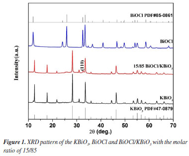
RESULTS AND DISCUSSION X-ray powder diffraction (XRD) analysis For pure KBiO3, it crystallizes in cubic KSbO3 type structure and the XRD patterns match well with the reported patterns for KBiO3 (PDF card No. 47-0879). For the pure BiOCl, all peaks can be indexed to the tetragonal system of BiOCl (PDF card No. 85-0861). For BiOCl/KBiO3 composites with the molar ratio of 15/85, all the diffraction peaks of KBiO3 can be found, and the intensity of the peaks become weaker due to the addition of BiOCl. The characteristic peak of BiOCl (110) can also be observed, but the intensity of the peak is very low because of the low content of BiOCl. Other characteristic peaks of BiOCl are not observed for the same reason. This result shows a coexistence of BiOCl and KBiO3 and suggests that BiOCl and KBiO3 are coupled together successfully.
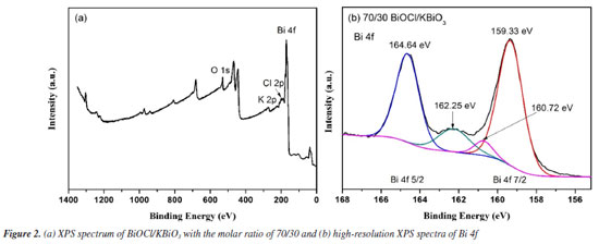
X-ray photoelectron spectroscopy (XPS) analysis The XPS spectrum of BiOCl/KBiO3 with the molar ratio of 70/30 is shown in Figure 2a. The special peaks in the figure demonstrate that the compound is composed of Bi, O, Cl and K elements. Figure 2b shows the characteristic peaks of Bi. The Bi 4f peak shows asymmetrical forms, and the Bi 4f 5/2 and Bi 4f 7/2 peaks are deconvoluted into two bimodal peaks at binding energies of 164.64 and 162.25 eV, and at 159.33 and 160.72 eV, respectively. This result indicates that both Bi3+ and Bi5+ exist in the BiOCl/KBiO3 with the molar ratio of 70/30. Both of the two bimodal peaks show very different intensities. This result can be explained by the very different contents of BiOCl and KBiO3 in the compound. Based on the results of XPS and XRD, it is believed that BiOCl/KBiO3 heterojunction composites are successfully synthesized.
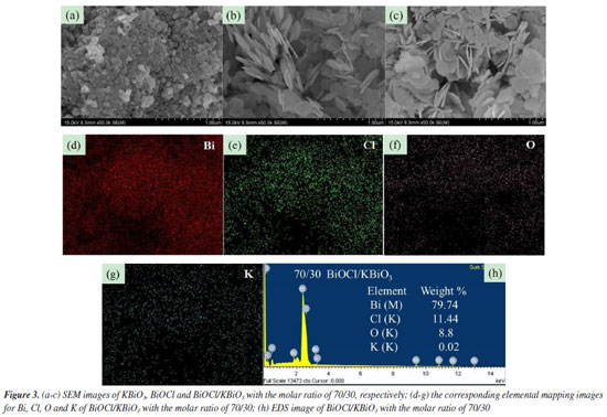
Scanning electron microscope (SEM) analysis The typical SEM images of KBiO3, BiOCl and BiOCl/KBiO3 with the molar ratio of 70/30 are shown in Figures 3a-3c. For pure KBiO3, it is composed of irregularly shaped particles with diameters of 50‑100 nm (Figure 3a). The pure BiOCl comprises many hierarchical mesoporous architectures45 (Figure 3b). BiOCl/KBiO3 with the molar ratio of 70/30 shows hierarchical mesoporous architectures which is similar to the pure BiOCl because of the larger content of BiOCl (Figure 3c). The structure provides a high surface area for BiOCl/ KBiO3 composites, suggesting its strong adsorption ability, and it is beneficial to the separation of photo generated electron-hole pairs. To further investigate elemental composition and distribution uniformity, the elemental maps of the selected area on BiOCl/KBiO3 with the molar ratio of 70/30 are displayed in Figures 3d‑3g, which indicates that homogeneous distribution of Bi, Cl, O and K constituting elements in the sample. These analyses indicate that BiOCl nanoplates are deposited on the surface of KBiO3 particles firmly. All these results further indicate the formation of heterojunctions between BiOCl and KBiO3. In addition, Figure 3h shows the chemical composition of BiOCl/KBiO3 with the molar ratio of 70/30 selected and examined by energy dispersive X-ray spectroscopy (EDS) analysis. The characteristic peaks prove the presence of Bi, Cl, O and K elements, which are also indicative of the BiOCl and KBiO3 components present in the system. No other impurity appears in the system. The Bi content is 79.74 wt.%, close to the theoretical weight (77.07 wt.%). In order to determine the element content more accurately, elemental analysis of the as-prepared samples was performed using inductively coupled plasma atomic emission spectroscopy (ICP-AES). Table 1 presents the actual percentage of K and Bi loaded in the structure of BiOCl/KBiO3 with the molar ratio of 70/30 and shows the Bi content is 76.4155 wt.%, closer to the theoretical weight (77.07 wt.%).

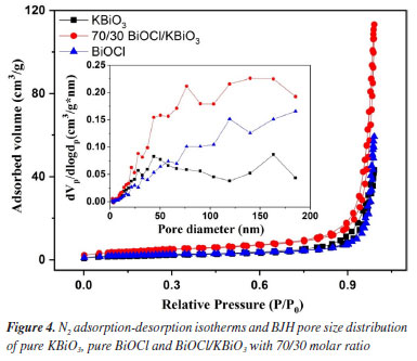
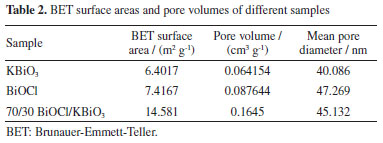
N2 adsorption-desorption analysis The N2 adsorption-desorption isotherms are measured for determining the surface area and porosity of the as-prepared samples. It is well known that the high specific surface area and mesoporous structure can improve the contact of organic pollutants to catalysts resulting in increased photocatalytic activity.46,47 Figure 4 shows N2 adsorption-desorption isotherms and Barrett-Joyner-Halenda (BJH) pore size distribution of the KBiO3, BiOCl and BiOCl/KBiO3 with the molar ratio of 70/30. According to Brunauer-Deming-Deming-Teller (BDDT) classification, the N2 adsorption-desorption isotherms of the KBiO3, BiOCl and BiOCl/KBiO3 with the molar ratio of 70/30 show the type IV curves and have the H3 hysteresis loops at the relative pressure of P/P0 between 0.6-1.0, especially for BiOCl and BiOCl/KBiO3. This originates from the textural porosity of the samples which could be caused by the stacking of the plates-like structure of the composite photocatalysts.45 This result is consistent with the SEM images. The specific surface area and porosity of the KBiO3, BiOCl and BiOCl/KBiO3 with the molar ratio of 70/30 are shown in Table 2. The BET surface area of BiOCl/KBiO3 is much higher than that of KBiO3 and BiOCl, indicating that the high specific surface area leads to the improvement of photocatalytic properties.
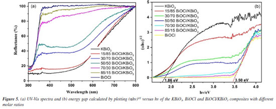
UV-Vis DRS analysis The optical properties of different samples were investigated by a UV-Vis diffuse reflectance spectrum (DRS), and the results obtained are shown in Figure 5a. The absorption edge of BiOCl occurs at about 370 nm. For KBiO3, a strong absorption is detected at wavelength shorter than around 550 nm and sharply declines from approximately 550 nm. The absorption spectra are consistent with the colors of the samples (Figure 6). As BiOCl builds up in the samples, the color becomes lighter. The phenomenon is ascribed to the interaction of heterojunction between BiOCl and KBiO3. The heterojunction can effectively improve the separation of photo-generated electron-hole pairs due to the band gap transition. The band gap (Eg) of semiconductors can be determined from DRS plots as follows:48 
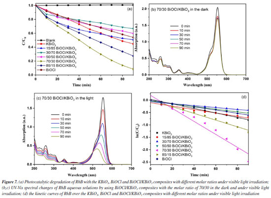
where α is the absorption coefficient, h is Planck constant, ν is light frequency, k is proportionality constant, Eg is the band gap energy. Among them, n is determined by the type of optical transition of a semiconductor (n = 2 for direct transition and n = 1/2 for indirect transition). According to the previous report,40 the n value of BiOCl and KBiO3 were all 1/2. From the plot of (αhn)1/2 versus hν in Figure 5b, the estimated band gap energies of the KBiO3 and BiOCl are 1.86 and 3.50 eV, respectively, which are consistent with previous reports.38,43 The band gap energies of the BiOCl/KBiO3 composites with different molar ratios are between those of KBiO3 and BiOCl. On the one hand, the higher band gap energy can inhibit the recombination of the photo-generated electron-hole pairs more effectively than KBiO3 with small band gap energy. On the other hand, it also can enhance the photocatalytic property theoretically. In addition, in Bi-oxides the chemical nature of spectator cation (Li+, Na+, K+, etc.) plays an important role in tailoring the band structure49 as also in stabilizing different oxidation states (+3 to +5) for Bi.39 Photocatalytic activity evaluation The photocatalytic activities of as-prepared samples are evaluated by the degradation of RhB under visible light (λ ≥ 400 nm). Figure 7a displays the photodegradation of RhB as a function of irradiation time over different photocatalysts. A blank experiment without catalysts demonstrates that the concentration of RhB have no noticeable change after irradiation for 90 min. For KBiO3, only 55.3% of the RhB was decomposed in 90 min. This suggests that the rapid recombination between conduction band (CB) electrons and valence band (VB) holes occurs mainly because of the narrow bandgap (1.86 eV) of KBiO3. The photodegradation of RhB with BiOCl is 45.9% after 90 min of irradiation with visible light although it cannot be activated by visible light due to the wide band gap. When comparing these BiOCl/KBiO3 samples, it is noteworthy that the photocatalytic activity of BiOCl/KBiO3 composites showed very different trends with the increasing amount of BiOCl. The BiOCl/KBiO3 sample with the molar ratio of 70/30 shows the highest photocatalytic activity of 91.6% RhB degradation in 90 min. The results indicate that until the suitable BiOCl content in BiOCl/KBiO3 composites, the photocatalytic activity is significantly enhanced, while it is decreased with excess BiOCl content. This may be attributed to the fact that the introduction of a large amount of BiOCl may lead to shielding of the active sites on the photocatalyst surface and weaken the intensity of light arrived to the reaction solution.50 Therefore, it is important to achieve a balance between the active trapping sites, which favoring the inhibition of the recombination of electron-hole pairs, and fewer trapped parts, which leading to a lower capacity for the separation of interfacial charge transfer.51
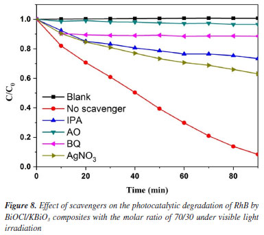
The temporal evolution of the absorption spectra during the RhB physisorption and photodegradation over the BiOCl/KBiO3 with the molar ratio of 70/30 in the dark and under visible light irradiation are shown in Figures 7b and 7c. It is well-known that RhB shows major absorption peak at 553 nm and the intensity of the peak in the spectrum decreases as the concentration of RhB decreases. About 16.9% of RhB decoloration is observed in the dark, which may be due to its plates-like mesoporous structure and large BET special surface. It indicates that the only dark adsorption of RhB with BiOCl/KBiO3 with the molar ratio of 70/30 is negligible. However, in the process of photodegradation within 90 min, it shows an apparently fast decrease in absorption with a concomitant wavelength shift of the band to shorter wavelengths. Under visible illumination, the dye is de-ethylated in a stepwise manner with the color of the dispersion changing from an initial red color to a light green-yellow. The fully de-ethylated RhB molecule has a major absorption band at λmax = 506 nm, in accordance with the standard spectra of RhB. The color of the dispersion disappeared after 90 min of irradiation, indicating that at least the chromophoric structure of the dye was destroyed.52 And no peak shift of RhB was detected indicating that no other intermediate was formed. To quantitatively investigate the reaction kinetics of RhB degradation in our experiment, the experimental data were fitted by applying a first-order model as expressed by Equation 2,53 which is well established for the photocatalytic experiments when the pollutant is in the millimolar concentration range.  where C0 and Ct are the concentrations of RhB in solution at times 0 and t, respectively, and k is the apparent first-order rate constant. The influence of the amount of BiOCl on the photodegradation rate of RhB over the KBiO3, BiOCl and BiOCl/KBiO3 composites with different molar ratios is shown in Figure 7d. From this figure, there is a linear relationship between ln(C0/Ct) and irradiation time, demonstrating that the photocatalytic reaction can depend quantitatively on the pseudo-first-order model.7 The reaction rate constants k of KBiO3, BiOCl/KBiO3 with the molar ratio of 15/85, 30/70, 50/50, 70/30, 85/15 and BiOCl are 0.00914, 0.00691, 0.00389, 0.00545, 0.02621, 0.01358, 0.00660 min-1, respectively. As shown in Figure 7d, when the molar ratio of BiOCl/KBiO3 composites is more than 50/50, the kinetic constants of BiOCl/KBiO3 composites for RhB degradation are higher than that of pure KBiO3 and BiOCl, and the BiOCl/KBiO3 composites with the molar ratio of 70/30 shows the highest value of k (0.02621 min-1), which is about 2.9 and 4.0 times higher than that of pure KBiO3 (0.00914 min-1) and pure BiOCl (0.00660 min-1), respectively. The result reveals that the optimum amount of BiOCl on KBiO3 could extremely facilitate the enhancement of photocatalytic activity of single KBiO3. Mechanism of enhanced photocatalytic activity In order to make sure the prime reactive species which are generated during photocatalytic oxidation process, p-benzoquinone (BQ, •O2– scavenger), isopropyl alcohol (IPA, •OH scavenger), ammonium oxalate monohydrate (AO, h+ scavenger) and AgNO3 (e– scavenger) with the amount of 1 mmol L-1 were added into the reaction system. The effects of four scavengers on the degradation of RhB in the presence of BiOCl/KBiO3 composites with the molar ratio of 70/30 under visible light irradiation are shown in Figure 8. Obviously, the percent of photocatalytic degradation of RhB decreased to nearly zero when AO was added and the similar phenomenon could be found when the BQ, IPA and AgNO3 were added. It indicates that h+, •O2-, ·OH and e- reactive species work together in combination for the photocatalytic degradation of RhB. This result is different from that described by Zhang et al.54
Based on the above results and discussions, in order to further research the separation process of photo-induced carriers, according to the results of DRS, the band edge positions of the valence band (VB) and conduction band (CB) of BiOCl/KBiO3 photo-catalysts can be estimated based on the following empirical equations:49  where EVB is the band edge positions of VB, ECB is the band edge positions of CB, X is the electronegativity of the semiconductor (which is the geometric mean of the electronegativity of the constituent atoms), Ee is the energy of free electrons on the hydrogen scale (4.5 eV) and Eg is the band gap energy of the semiconductor. As mentioned above, the band gap of KBiO3 and BiOCl is 1.86 and 3.50 eV, respectively. From the above empirical formula, the EVB of KBiO3 and BiOCl is estimated to be 1.89 and 3.90 eV, respectively and the corresponding ECB of KBiO3 and BiOCl is calculated to be 0.03 and 0.40 eV, respectively, as shown in Table 3. The band edge positions of KBiO3 and BiOCl show band alignment as schematically illustrated in Figure 9. As displayed in Figure 9a, the Fermi level and CB of BiOCl are little lower than that of KBiO3 before they are in contact. The Fermi levels of p-type BiOCl is near below, while the Fermi levels of n-type KBiO3 is near above, which seems to be hard to conduct the photocatalytic reaction. However, according to the general p-n heterojunction formation process reported in literatures,55,56 when the p-n heterojunction is formed between KBiO3 and BiOCl, the Fermi levels of KBiO3 and BiOCl tend to descend and rise up to achieve an equilibrium state, and an inner electric field will be formed in the interface of p-n heterojunction. The inner electric field makes the region of BiOCl have negative charges, while the region of KBiO3 has positive charges. In comparison, the conduction band and valence band position of BiOCl are all more negative than that of KBiO3. Under visible light irradiation, only KBiO3 can be activated to generate electron-hole pairs. The inner electric field at p-n heterojunction interface will push the photogenerated holes on the VB of KBiO3 toward that of BiOCl, while the electrons still remain on the CB of KBiO3. In such a way, the photo-induced electrons and holes are efficiently separated and the recombination of electron-hole pairs is hindered.49 In addition, the valence band edge potential of BiOCl is more negative than E0(•OH/H2O) (2.27 VNHE) or E0(OH/HO–) (2.38 VNHE),56 suggesting that the photo-induced holes (h+) on the VB of BiOCl cannot react with H2O or OH– to form •OH. Thus, the photo-induced holes h+ on the VB of BiOCl are consumed to oxide RhB molecules directly. However, the conduction band edge of KBiO3 is less negative than E0(O2/•O2) (–0.33 VNHE) and E0(O2/•HO2) (–0.05 VNHE).57 Therefore, it cannot provide a sufficient potential to reduce O2 through the one-electron reduction process and further form •OH. Therefore, it is reasonable for O2 to react with electrons on the CB of KBiO3 to generate H2O2 (Equation 5) via a two-electron reduction reaction process58-62 (E0(O2/H2O2) = +0.695 VNHE).61 Then the formed H2O2 quickly reacts with an electron to finally form •OH (Equation 6),63 which are highly oxidative active species to many organic pollutants. At the same time, under visible light irradiation RhB molecules can be photosensitized55 and electrons immediately transfer from the excited states of the adsorbed dyes to the conduction band of BiOCl with more negative potential than E0(O2/•O2). Thus, the photosensitized electrons also participate in the oxidation process through the reduction of the adsorbed O2 on the surface of the catalyst to the superoxide radical •O2– (Equation 7). In conclusion the photo-induced holes (h+), hydroxyl radicals (·OH) and superoxide radical (•O2–) which all have strong oxidizing ability for organics work together to break down the chromophores of RhB dye into small molecules, e.g., H2O and CO2.64-70 The process is in good agreement with the results of trapping experiment. This result is also different from that described by Zhang et al.54 The specific reasons need to be further studied in subsequent experiments. 
CONCLUSIONS In summary, BiOCl/KBiO3 p-n heterostructures were successfully synthesized via a facile in situ method. The photocatalytic performance of the as-prepared BiOCl/KBiO3 composites showed very different trends with the increasing amount of BiOCl. BiOCl/KBiO3 composites with the molar ratio of 70/30 exhibited the highest photocatalytic activity for the degradation of RhB under visible light irradiation due to its large surface area, excellent charge separation characteristics and the suppressed recombination of electron-hole pairs. In addition, a possible and new mechanism of the degradation over BiOCl/KBiO3 p-n heterojunction photocatalyst was proposed in detail.
SUPPLEMENTARY MATERIAL Complementary material for this work is available at http://quimicanova.sbq.org.br/, as a PDF file, with free access.
ACKNOWLEDGMENTS This research was supported by Scientific Research Foundation for the Returned Overseas Chinese Scholars, Hebei Province (C20210101), the Foundation of Hebei Minzu Normal University (DR2022007), the Introduces Foreign Intelligence Projects of Hebei Province (No. 130800), S & T Program of Chengde (No. 202205B090) and China Scholarship Council (CSC) grant #202108130124.
REFERENCES 1. Asahi, R.; Morikawa, T.; Ohwaki, T.; Aoki, K.; Taga, Y.; Science 2001, 293, 269. [Crossref] 2. Chong, M. N.; Jin, B.; Chow, C. W. K.; Saint, C.; Water Res. 2010, 44, 2997. [Crossref] 3. Dai, F.; Zai, J. T.; Yi, R.; Gordin, M. L.; Sohn, H.; Chen, S. R.; Wang, D. H.; Nat. Commun. 2014, 5, 3605. [Crossref] 4. Gao, K.; Li, S. D.; Appl. Surf. Sci. 2012, 258, 6460. [Crossref] 5. Zhang, Y.; Zhao, Z. Y.; Chen, J. R.; Cheng, L.; Chang, J.; Sheng, W. C.; Hu, C. Y.; Cao, S. S.; Appl. Catal., B 2015, 165, 715. [Crossref] 6. Zheng, X. Z.; Li, D. Z.; Li, X. F.; Chen, J.; Cao, C. S.; Fang, J. L.; Wang, J. B.; He, Y. H.; Zheng, Y.; Appl. Catal., B 2015, 168, 408. [Crossref] 7. Song, H. B.; Wu, R. Y.; Yang, J. F.; Dong, J. C.; Ji, G. J.; J. Colloid Interface Sci. 2018, 512, 325. [Crossref] 8. Zhou, L.; Wang, W. Z.; Liu, S. W.; Zhang, L. S.; Xu, H. L.; Zhu, W.; J.Mol. Catal. A: Chem. 2006, 252, 120. [Crossref] 9. Dong, S. Y.; Yu, C. F.; Li, Y. K.; Li, Y. H.; Sun, J. H.; Geng, X. F.; J. Solid State Chem. 2014, 211, 176. [Crossref] 10. Thalluri, S. M.; Hussain, M.; Saracco, G.; Barber, J.; Russo, N.; Ind. Eng. Chem. Res. 2014, 53, 2640. [Crossref] 11. Li, R. G.; Han, H. X.; Zhang, F. X.; Wang, D. G.; Li, C.; Energy Environ. Sci. 2014, 7, 1369. [Crossref] 12. Chala, S.; Wetchakun, K.; Phanichphant, S.; Inceesungvorn, B.; Wetchakun, N.; J. Alloys Compd. 2014, 597, 129. [Crossref] 13. Yu, J. G.; Xiong, J. F.; Cheng, B.; Yu, Y.; Wang, J. B.; J. Solid State Chem. 2005, 178, 1968. [Crossref] 14. He, Z.; Sun, C.; Yang, S. G.; Ding, Y. C.; He, H.; Wang, L. Z.; J. Hazard. Mater. 2009, 162, 1477. [Crossref] 15. Fu, G. K.; Xu, G. N.; Chen, S. P.; Lei, L.; Zhang, M. L.; Catal. Commun. 2013, 40, 120. [Crossref] 16. Nithya, V. D.; Selvan, R. K.; Kalpana, D.; Vasylechko, L.; Sanjeeviraja, C.; Electrochim. Acta 2013, 109, 720. [Crossref] 17. Saison, T.; Gras, P.; Chemin, N.; Chaneac, C.; Durupthy, O.; Brezova, V.; Colbeau-Justin, C.; Jolivet, J. P.; J. Phys. Chem. C 2013, 117, 22656. [Crossref] 18. Yan, Y.; Wu, Y. F.; Yan, Y. T.; Guan, W. S.; Shi, W. D.; J. Phys. Chem. C 2013, 117, 20017. [Crossref] 19. Zhao, G.; Liu, S. W.; Lu, Q. F.; Xu, F. X.; Sun, H. Y.; J. Alloys Compd. 2013, 578, 12. [Crossref] 20. Zhang, L. S.; Wang, W. Z.; Yang, J. O.; Chen, Z. G.; Zhang, W. Q.; Zhou, L.; Liu, S. W.; Appl. Catal., A 2006, 308, 105. [Crossref] 21. Huo, Y. N.; Jin, Y.; Zhang, Y.; J. Mol. Catal. A: Chem. 2010, 331, 15. [Crossref] 22. Huo, Y. N.; Miao, M.; Zhang, Y.; Zhu, J. A.; Li, H. X.; Chem. Commun. 2011, 47, 2089. [Crossref] 23. Bhunia, M. K.; Das, S. K.; Dutta, A.; Sengupta, A.; Bhaumik, A.; J. Nanosci. Nanotechnol. 2013, 13, 2557. [Crossref] 24. Yao, W. F.; Wang, H.; Xu, X. H.; Zhang, Y.; Yang, X. N.; Shang, S. X.; Liu, Y. H.; Zhou, J. T.; Wang, M.; J. Mol. Catal. A: Chem. 2003, 202, 305. [Crossref] 25. Lin, T.; Pi, Z.; Gong, M. C.; Zhong, J. B.; Wang, J. L.; Chen, Y. Q.; Chin. Chem. Lett. 2007, 18, 241. [Crossref] 26. Xu, S. H.; Shangguan, W. F.; Yuan, J.; Shi, J. W.; Chen, M. X.; Mat. Sci. Eng., B 2007, 137, 108. [Crossref] 27. Zhou, J. K.; Zou, Z. G.; Ray, A. K.; Zhao, X. S.; Ind. Eng. Chem. Res. 2007, 46, 745. [Crossref] 28. Kim, B. H.; Lim, T. H.; Roh, J. W.; Lee, S. G.; Ju, C. S.; Park, S. S.; Hong, S. S.; Lee, G. D.; React. Kinet., Mech. Catal. 2010, 99, 217. [Crossref] 29. Hou, J. G.; Cao, R.; Jiao, S. Q.; Zhu, H. M.; Kumar, R. V.; Appl. Catal., B 2011, 104, 399. [Crossref] 30. Wei, J. Y.; Huang, B. B.; Wang, P.; Wang, Z. Y.; Qin, X. Y.; Zhang, X. Y.; Jing, X. Y.; Liu, H. X.; Yu, J. X.; Int. J. Photoenergy 2012, 2012, 135132. [Crossref] 31. Dolgos, M. R.; Paraskos, A. M.; Stoltzfus, M. W.; Yarnell, S. C.; Woodward, P. M.; J. Solid State Chem. 2009, 182, 1964. [Crossref] 32. Nakamura, H.; Ishii, S.; Yamada, K.; Matsushima, S.; Arai, M.; Kobayashi, K.; Mater. Chem. Phys. 2010, 121, 385. [Crossref] 33. Li, Y. X.; Chen, G.; Zhang, H. J.; Li, Z. H.; Sun, J. X.; J. Solid State Chem. 2008, 181, 2653. [Crossref] 34. Kako, T.; Ye, J. H.; Mater. Trans. 2005, 46, 2694. [Crossref] 35. Tang, J. W.; Zou, Z. G.; Ye, J. H.; Catal. Lett. 2004, 92, 53. [Crossref] 36. Jiang, R.; Zhu, H. Y.; Li, J. B.; Fu, F. Q.; Yao, J.; Jiang, S. T.; Zeng, G. M.; Appl. Surf. Sci. 2016, 364, 604. [Crossref] 37. Takei, T.; Haramoto, R.; Dong, Q.; Kumada, N.; Yonesaki, Y.; Kinomura, N.; Mano, T.; Nishimoto, S.; Kameshima, Y.; Miyake, M.; J. Solid State Chem. 2011, 184, 2017. [Crossref] 38. Ramachandran, R.; Sathiya, M.; Ramesha, K.; Prakash, A. S.; Madras, G.; Shukla, A. K.; J. Chem. Sci. 2011, 123, 517. [Crossref] 39. Zheng, H. X.; Zhang, T. T.; Zhu, Y. M.; Liang, B.; Jiang, W.; ChemPhotoChem 2018, 2, 442. [Crossref] 40. Xie, T. P.; Xu, L. J.; Liu, C. L.; Yang, J.; Wang, M.; Dalton Trans. 2014, 43, 2211. [Crossref] 41. Wang, K. X.; Shao, C. L.; Li, X. H.; Miao, F. J.; Lu, N.; Liu, Y. C.; J. Sol-Gel Sci. Technol. 2016, 80, 783. [Crossref] 42. Xiang, Y. H.; Ju, P.; Wang, Y.; Sun, Y.; Zhang, D.; Yu, J. Q.; Chem. Eng. J. 2016, 288, 264. [Crossref] 43. Zhang, K. L.; Liu, C. M.; Huang, F. Q.; Zheng, C.; Wang, W. D.; Appl. Catal., B 2006, 68, 125. [Crossref] 44. Chang, X. F.; Yu, G.; Huang, J.; Li, Z.; Zhu, S. F.; Yu, P. F.; Cheng, C.; Deng, S. B.; Ji, G. B.; Catal. Today 2010, 153, 193. [Crossref] 45. Cheng, H. F.; Huang, B. B.; Qin, X. Y.; Zhang, X. Y.; Dai, Y.; Chem. Commun. 2012, 48, 97. [Crossref] 46. Liu, Y. B.; Zhu, G. Q.; Gao, J. Z.; Hojamberdiev, M.; Lu, H. B.; Zhu, R. L.; Wei, X. M.; Liu, P.; J. Alloys Compd. 2016, 688, 487. [Crossref] 47. Aslam, I.; Cao, C. B.; Tanveer, M.; Farooq, M. H.; Khan, W. S.; Tahir, M.; Idrees, F.; Khalid, S.; RSC Adv. 2015, 5, 6019. [Crossref] 48. Zou, X. J.; Dong, Y. Y.; Zhang, X. D.; Cui, Y. B.; Ou, X. X.; Qi, X. H.; Appl. Surf. Sci. 2017, 391, 525. [Crossref] 49. Sleight, A. W.; Prog. Solid State Chem. 2009, 37, 251. [Crossref] 50. Liu, Y.; Yuan, X. Z.; Wang, H.; Chen, X. H.; Gu, S. S.; Jiang, Q.; Wu, Z. B.; Jiang, L. B.; Wu, Y.; Zeng, G. M.; Catal. Commun. 2015, 70, 17. [Crossref] 51. Han, C. C.; Ge, L.; Chen, C. F.; Li, Y. J.; Zhao, Z.; Xiao, X. L.; Li, Z. L.; Zhang, J. L.; J. Mater. Chem. A 2014, 2, 12594. [Crossref] 52. Fu, H. B.; Pan, C. S.; Yao, W. Q.; Zhu, Y. F.; J. Phys. Chem. B 2005, 109, 22432. [Crossref] 53. Zhao, W.; Dai, B. L.; Zhu, F. X.; Tu, X. Y.; Xu, J. M.; Zhang, L. L.; Li, S. Y.; Leung, D. Y. C.; Cheng, S.; Appl. Catal., B 2018, 229, 171. [Crossref] 54. Zhang, H.; Zheng, H.; Wang, Y.; Yan, R. H.; Luo, D. Y.; Jiang, W.; Ind. Eng. Chem. Res. 2019, 58, 1875. [Crossref] 55. Zhang, N.; Xu, Y. J.; Chem. Mater. 2013, 25, 1979. [Crossref] 56. Jiang, J.; Zhang, X.; Sun, P. B.; Zhang, L. Z.; J. Phys. Chem. C 2011, 115, 20555. [Crossref] 57. Zou, X. J.; Dong, Y. Y.; Zhang, X. D.; Cui, Y. B.; Appl. Surf. Sci. 2016, 366, 173. [Crossref] 58. Bi, Y. P.; Ouyang, S. X.; Cao, J. Y.; Ye, J. H.; Phys. Chem. Chem. Phys. 2011, 13, 10071. [Crossref] 59. Kim, J. W.; Lee, C. W.; Choi, W.; Environ. Sci. Technol. 2010, 44, 6849. [Crossref] 60. Tatsuma, T.; Takada, K.; Miyazaki, T.; Adv. Mater. 2007, 19, 1249. [Crossref] 61. Antoniadou, M.; Lianos, P.; Appl. Catal., B 2010, 99, 307. [Crossref] 62. Ueno, H.; Nemoto, J.; Ohnuki, K.; Horikawa, M.; Hoshino, M.; Kaneko, M.; J. Appl. Electrochem. 2009, 39, 1897. [Crossref] 63. Cao, J.; Luo, B. D.; Lin, H. I.; Xu, B. Y.; Chen, S. F.; J. Hazard. Mater. 2012, 217-218, 107. [Crossref] 64. Wang, H. L.; Zhang, L. S.; Chen, Z. G.; Hu, J. Q.; Li, S. J.; Wang, Z. H.; Liu, J. S.; Wang, X. C.; Chem. Soc. Rev. 2014, 43, 5234. [Crossref] 65. Zhang, J. L.; Zhang, L. S.; Shen, X. F.; Xu, P. F.; Liu, J. S.; CrystEngComm 2016, 18, 3856. [Crossref] 66. Wang, H. L.; Li, S. J.; Zhang, L. S.; Chen, Z. G.; Hu, J. Q.; Zou, R. J.; Xu, K. B.; Song, G. S.; Zhao, H. H.; Yang, J. M.; Liu, J. S.; CrystEngComm 2013, 15, 9011. [Crossref] 67. Kharatzadeh, A.; Jamali-Sheini, F.; Yousefi, R.; Mater. Des. 2016, 107, 47. [Crossref] 68. Yousefi, R.; Jamali-Sheini, F.; Cheraghizade, M.; Zaman, L.; Mater. Res. Innovations 2016, 20, 121. [Crossref] 69. Zinatloo-Ajabshir, S.; Salavati-Niasari, M.; Zinatloo-Ajabshir, Z.; Mater. Lett. 2016, 180, 27. [Crossref] 70. Morassaei, M. S.; Zinatloo-Ajabshir, S.; Salavati-Niasari, M.; J. Mol. Liq. 2016, 220, 902. [Crossref] |
On-line version ISSN 1678-7064 Printed version ISSN 0100-4042
Qu�mica Nova
Publica��es da Sociedade Brasileira de Qu�mica
Caixa Postal: 26037
05513-970 S�o Paulo - SP
Tel/Fax: +55.11.3032.2299/+55.11.3814.3602
Free access


