
 |
 |
 |
 |
 |
Artigo
| Microenvironment modulation of TiO2 nanosheets for highly selective photocatalytic CO2 reduction |
|
Xingxing Zheng* Department of Chemistry, College of Chemistry and Material Science, Jinan University, 510632 Guangzhou, China Received: 08/16/2024 *e-mail: xing1003@stu2022.jnu.edu.cn; tyangj@jnu.edu.cn Photocatalytic reduction of CO2 and H2O into valuable fuels is a promising and sustainable approach. Phosphate is crucial for the production of ATP (adenosine triphosphate), highlighting its significance in the transfer of energy essential for life. In this study, we design and prepare a modified TiO2 surface with phosphate to reduce CO2 using light. The TiO2+PO43- composite performs exceptionally well, producing CO at a rate of 36.93 μmol g-1 h-1, which is three times higher than pure TiO2, with nearly 100% selectivity for CO. Both experiments and theoretical analyses show that the phosphorus species create a channel for electron transfer between PO43- and Ti, improving charge movement. Modification by phosphate ions (PO43-) alters the surface microenvironment of TiO2, making it easier for more water molecules to be adsorbed on the surface. Furthermore, the PO43- modification adds more oxygen-containing functional groups to the surface. These groups act as sites that help in capturing and activating CO2. As a result, TiO2+PO43- stands out as a strong candidate for CO2 reduction, thanks to better charge transfer and more active sites. INTRODUCTION The growth of the human industrial society has led to the extensive burning of fossil fuels,1 which not only worsens the greenhouse effect but also triggers an energy crisis.2 Although artificial photocatalytic technology has the potential to harness solar energy for converting carbon dioxide into valuable hydrocarbon fuels, there are still significant limitations with artificial photocatalysts. These include low efficiency in the separation of photogenerated charges and holes, and their overall performance remains far below that of natural enzymes found in the biosphere. Common photocatalysts include inorganic materials such as CdS,3 perovskites,4 and TiO2,5 SrWO3,6 Cu2O,7 which fundamentally differ from the photocatalytic action of natural enzymes in the biosphere. TiO2 has garnered significant attention as a photocatalyst in the field of photocatalysis due to its non-toxicity8 and structural stability.9 In recent years, researchers have explored various methods to enhance the photocatalytic activity of TiO2, including doping,10 loading,11 and regulating its shape.12 For instance, we proposed a method to modify the surface of TiO2 with phosphate to improve the separation of photogenerated electrons and holes. Photocatalytic technology has emerged as a promising strategy for addressing global warming and energy crises by converting carbon dioxide into valuable chemicals and fuels.13 Given the importance of achieving sustainable carbon-neutral economic development, highly efficient, selective, and stable photocatalytic CO2 reduction systems are extremely valuable. In the photocatalytic CO2 reduction process, photogenerated charges and holes tend to recombination due to Coulombic forces,14 which reduces the efficiency of CO2 reduction and affects the adsorption and reaction sites of CO2 and H2O on the catalyst surface.15 Recently, researchers have effectively inhibited the recombination of photogenerated charges by constructing heterostructures,16 doping,17 designing active sites,18 and optimizing structures,19 thereby reducing CO2 reduction. Prior to these developments, efforts were focused on finding CO2 reduction systems with high selectivity for easier product separation. For instance, Yu and co-workers20 proposed that the S-type heterojunction effectively promotes the separation of photogenerated electrons and holes by constructing an internal electric field, which reduced their recombination rate. Additionally, by designing catalysts with multilayer structures or nanostructures, the light absorption efficiency is improved, leading to enhanced photocatalytic activity. Zhang and co-workers21 proposed a melting strategy for synthesizing uniformly doped BiOCl nanosheets with exceptional stability and high selectivity. This method enabled the reconstruction of the BiOCl surface, resulting in closely packed B-oxygen vacancy (B-OV) complexes. These complexes exhibited a remarkable selectivity of 98% for CO2 reduction to CO, with a reduction rate of 83.64 μmol g-1 h-1. Liu and co-workers22 synthesized ultrathin Cu4(SO4)(OH)6 nanosheets and observed them to undergo a cascaded electron transfer process based on d-d orbital transitions by infrared illumination. Song and co-workers23 synthesized TiO2 nanosheets modified with varying concentrations of sulfuric acid through hydrothermal treatment. The enhanced photocatalytic activity was attributed to the acidification, which promoted the formation of hydroxyl (Brønsted acidic sites) and oxygen vacancy/Ti3+ species. This improvement facilitated effective charge separation and transfer to the TiO2 surface to achieve the highest activity for CO2 photocatalytic reduction to CH4 at 3.3 μmol g-1 h-1. The active sites24 and microenvironment25 of the catalyst are crucial in regulating the chemical selectivity of CO2 reduction. However, reports on how to control these two aspects to enhance selectivity are still relatively limited. In this study, we propose a novel approach to enhance the photocatalytic activity and selectivity of TiO2 nanosheets through phosphate modification. By combining with PO43- ions, we transform TiO2 nanosheets into a novel active substance that demonstrates exceptional photocatalytic performance for CO2 conversion to CO. The rate of CO gas evolution reaches up to 36.93 μmol g-1 h-1, which is approximately three times higher than that of the original TiO2. Additionally, the selectivity for carbon-based products is nearly 100%. It is proposed that PO43- can not only adsorb on the TiO2 surface to form TiO2+PO43- but also create a unique microenvironment around the catalyst. Theoretical calculations using molecular dynamics (MD) simulation suggest that this microenvironment improve the adsorption of H2O. Both experimental and theoretical analyses indicate that the PO43- rich microenvironment enhances the mass transfer of H2O to the active site. Our finding demonstrates that PO43- can regulate the active site of the photocatalyst and create a mildly alkaline microenvironment. This environment enhances CO2 adsorption and water dissociation, ultimately promoting the separation of photogenerated charges and holes, thereby improving the efficiency of photocatalytic reduction.
EXPERIMENTAL Reagent and solutions We employed top-tier, analytical-grade reagents without additional purification. Ultrapure water, with a resistivity of over 18 MΩ cm, was the medium for solution preparation. High-purity CO2 (99.99%), hydrogen and argon (with hydrogen accounting for 5%) were sourced from GQ Gas-Unicare. Our primary photocatalyst, titanium dioxide (TiO2, 99.9% pure), was procured from Aladdin Reagent Co., Ltd., China. Phosphoric acid (≥ 85 wt.% in H2O) and sodium phosphate (Na3PO4·12H2O, ≥ 98%), sodium dihydrogen phosphate (NaH2PO4·H2O, ≥ 98%), dibasic sodium phosphate (Na2HPO4·12H2O, ≥ 98%) were obtained from Sinopharm Chemical Reagent Co., Ltd., China. The Nafion solution (5 wt.%) for electrode fabrication was acquired from Sigma-Aldrich. Material fabrication First, commercial TiO2 was calcined at 300 ºC in the air atmosphere for 8 h to remove any possible carbon residues. Another 0.5 g of calcined titanium dioxide was divided into four portions, which were added to. 40 mL of 0.3 M phosphoric acid, sodium dihydrogen phosphate, disodium hydrogen phosphate, and sodium phosphate, respectively. The samples were ultrasonicated for 5 min to make the titanium dioxide disperse more evenly. They were shaken on a shaker for 24 h, then centrifuged and washed with water to remove unstable ions and dried in a vacuum oven at 60 ºC overnight. Finally, the samples were grounded and each one was placed in a crucible that was subsequently wrapped in tin foil. In an environment of hydrogen and argon (with hydrogen accounting for 5%), the samples were calcined at 300 ºC for 2 h. The original sample after calcination is marked as TiO2, and the samples after impregnation and calcination are marked as TiO2+Na3PO4, TiO2+Na2HPO4, TiO2+NaH2PO4, and TiO2+H3PO4. Characterization Powder X-ray diffraction (XRD) analysis was investigated on the Rigaku MiniFlex 600 analyzer using Cu Kα radiation (λ = 1.54056 Å) and with the range of 2θ being from 10º to 70º, the step length being 0.02º, and the scanning speed being 10º min-1. Morphological insights were gleaned through JEM-2100F TEM (20KV) and HRTEM, revealing nanoscale details. UV-Vis diffuse reflectance spectra (DRS) were captured using a Cary4000 spectrophotometer, with BaSO4 as the reflectance standard. Elemental and chemical state analysis was achieved via ESCALAB 250 XPS with Al-Kα radiation, using C 1s (284.8 eV) as a reference. Photoluminescence behavior was probed with a Shimadzu RF-5301PC, unveiling electron transition dynamics. The photocurrent and electrochemical impedance spectroscopy (EIS), measured on a CHI 760 workstation with a 0.1 M Na2SO4 electrolyte, affirmed the electrochemical activity, encapsulating a comprehensive materials characterization. Photocatalytic test A 5.0 mg catalyst is dispersed in 400 μL deionized water and sonicated to form a suspension, then applied to a 3.5 cm slide, air-dried. This slide is placed in a 135 mL chamber, and 100 μL deionized water is added as a hydrogen source. The chamber is sealed with a quartz lid, purged with 99.9% CO2 for 15 min. Finally, the reactor was exposed to simulated sunlight (PLS-SXE300D), with a light intensity of approximately 200 mW cm-2. Gaseous samples were collected hourly and analyzed using gas chromatography (Shimadzu GC-2014A) equipped with a conductivity detector (TCD) and a flame ionization detector (FID). It was used a Hamilton gas - tight syringe (500 μL) to measure the generated gas at 60-min intervals. Additionally, for each time interval, a 500 μL sample from the reactor headspace was collected.
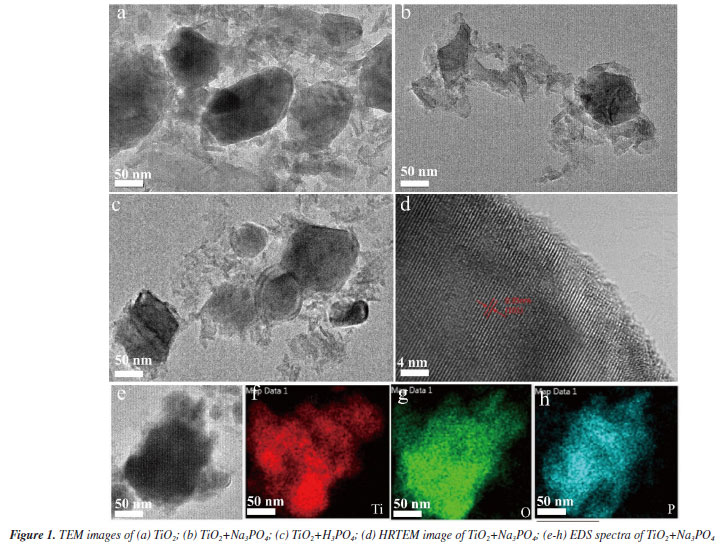
RESULTS AND DISCUSSION Characterization of the samples was performed using transmission electron microscopy (TEM) and high-resolution transmission electron microscopy (HRTEM) to determine their microcrystalline size, microstructure, and elemental composition. The TiO2 samples exhibited larger grain sizes compared to those of TiO2+Na3PO4 and TiO2+H3PO4 (Figures 1a-1c). Studies have shown that phosphate groups can effectively hinder the aggregation and further growth of microcrystals.26 This indicates that TiO2 has been modified by phosphate groups and that these groups can firmly connect to the surface of the microcrystals prepared. Figure 1d shows an HRTEM image of TiO2+Na3PO4, where the microcrystalline size is approximately 35 nm, and the clear d-spacing of 0.35 nm obtained from TiO2+Na3PO4 is consistent with the (101) plane of the anatase-type TiO2.8 The EDS images of TiO2+Na3PO4 indicate that element P is uniformly dispersed on the TiO2 surface (Figures 1e-1h).
The X-ray diffraction (XRD) analysis of the sample's phase structure (Figure 2a) reveals several typical peaks with 2θ values of 25.1º, 38.6º, 46.4º, and 55.1º that match the anatase lattice parameters (JCPDS No. 75-1537).4 The XRD analysis shows that the peak positions, half-peak widths, and peak intensities of TiO2 are consistent with those of the TiO2 surface-modified samples (TiO2+Na3PO4, TiO2+Na2HPO4, TiO2+NaH2PO4, TiO2+H3PO4), indicating that they all have good crystallinity. This suggests that the modification is limited to the TiO2 surface and does not alter the TiO2 crystal phase, which is consistent with the TEM results.
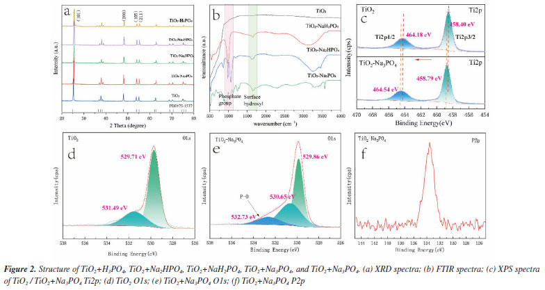
Figure 2b shows the Fourier transform infrared spectra (FTIR) of TiO2+H3PO4, TiO2+Na2HPO4, TiO2+NaH2PO4, TiO2+Na3PO4, and TiO2. The absorption peak at approximately 1630 cm-1 corresponds to the bending vibration mode of the hydroxyl group (O-H).27 Furthermore, the combination of TiO2 and PO43- exhibits the strongest absorption peak at 1630 cm-1. This suggests that the treatment with PO43- increases the number of surface hydroxyl functional groups on TiO2, which provides Lewis basic sites for adsorbing and activating the CO2 reactant. This finding aligns with the results shown in CO2-TPD (Figure 4S, Supplementary Material), indicating that TiO2 modified with PO43- is more effective at adsorbing CO2 compared to pure TiO2. Thus, the phosphate modification enhances the material's ability to capture more reactants. When combined with the XPS data for O 1s mentioned earlier (Figure 2e), the modification with PO43- leads to the formation of more oxygen-containing substances. These substances have an increased number of lone pair electrons, which create Lewis basic sites that can effectively adsorb and activate CO2 molecules. Around 3400 cm-1, this absorption peak generally corresponds to the stretching vibration of the hydroxyl bond (O-H).28 Notably, the intensity of the infrared peak at approximately 1630 cm-1 is heightened for the TiO2 surface modified with phosphate, indicating an increase in the number of surface hydroxyl groups, which is beneficial for water molecule adsorption. In the range of 900-1200 cm-1,29 phosphate groups primarily exhibit the stretching vibration mode of the phospho-oxygen bond (P-O). The characteristic peaks within this region are typically linked to two types of stretching vibration: the symmetric stretching vibration (ν1) and asymmetric stretching vibration (ν3) of the phosphate ion (PO43-).30 To identify the chemical state of the elements on the surface of the photocatalyst, X-ray photoelectron spectroscopy (XPS) measurements were conducted. The O1s spectrum of TiO2 can be decomposed into two peaks at 529.71 and 531.49 eV, corresponding to the lattice oxygen and surface hydroxyl groups of TiO2 (Figure 2d).31 For Na3PO4+TiO2, the O1s spectrum shows three peaks at 529.86, 530.65, and 532.73 eV (Figure 2e), corresponding to the lattice oxygen and surface hydroxyl groups of TiO2, as well as the P=O groups of the modified PO43-. This indicates that the PO43- has been modified onto the TiO2 surface. The Ti2p XPS spectra of TiO2 and TiO2+Na3PO4 (Figure 2c) show an increase in the Ti2p binding energy for the latter, which may be due to the formation of bonds between the O in PO43- and Ti, with electron transfer from Ti to PO43-, which is consistent with the density functional theory (DFT) calculations (Figure 4a). The P2p XPS spectrum of TiO2+Na3PO4 peaks at approximately 133.6 eV (Figure 2f), which belongs to P5+,32 further confirming that the PO43- has been modified to the TiO2 surface.
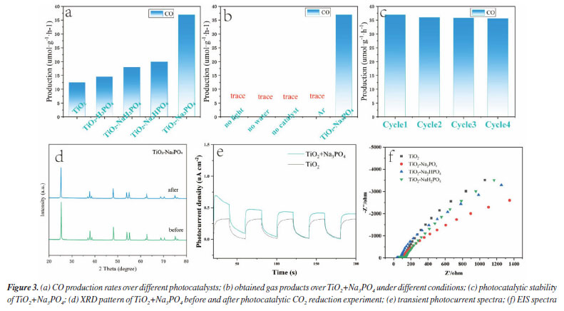
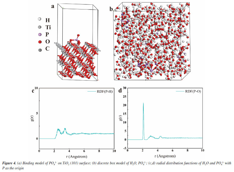
As shown in Figure 3a, we demonstrate that we have modified the phosphate group onto the surface of titanium dioxide. This modification resulted in a carbon monoxide (CO) production rate of 36.93 μmol g-1 h-1, which is approximately 3 times higher than that of the unmodified titanium dioxide, which produced 12 μmol g-1 h-1. The blank control experiment, illustrated in Figure 3b, showed that no CO generated during under conditions lacking H2O, CO2, catalyst, and argon gas flow. This confirms that the CO generated during the Na3PO4+TiO2 photocatalytic reaction originates form CO2. In the stability test presented in Figure 3c, the CO production of Na3PO4+TiO2 remained nearly constant after four performance tests. This indicates that the photocatalytic stability of Na3PO4+TiO2 was well-maintained. Moreover, the XRD patterns of Na3PO4+TiO2, shown in Figure 3d, indicate that there were no change in peak position, half-width, or intensity before and after the photocatalytic reaction. This highlights that crystal phase of Na3PO4+TiO2 remained unchanged, further confirming stability of the Na3PO4+TiO2 photocatalysis. Transient photocurrent is commonly used to analyze the efficiency of charge separation and transport in photocatalysts.33 We analyzed by detecting the difference in the instantaneous photocurrent density during a 20-s interval between turning on and off the light, with a larger difference indicating better charge separation efficiency. As shown in Figure 3e, the transient photocurrent density difference of TiO2+Na3PO4 during the alternation of light and darkness was the maximum, indicating that the modification of TiO2 surface with PO43- was beneficial for the separation of photogenerated electrons and holes. EIS was utilized to investigate the efficiency of charge separation and transport in photocatalysts.34 In the EIS spectrum, the radius of the curve indicates the charge transfer resistance at the interface of the electrode material and electrolyte interface, a smaller radius suggests lower resistance and faster charge transport. As shown in Figure 3f, the radius of the curve for TiO2+Na3PO4 was the smallest. Additionally, there was a noticeable reduction in radius after the modification of TiO2 with other phosphate salts. This indicates that the surface modification of TiO2 with phosphate salts enhances charge transport and separation of photogenerated electrons and holes, thereby decreasing their recombination. Among the tested modifications, TiO2+Na3PO4 exhibited the most significant effect. In addition to using transient photocurrent and EIS to study the charge transport efficiency and separation effect in the photocatalytic process, steady-state fluorescence spectroscopy can also be employed.35 When photogenerated electrons and holes recombine, fluorescence emission occurs. A lower fluorescence intensity indicates reduced recombination of photogenerated electrons and holes, which reflects better separation efficiency. As shown in Figure 5S (Supplementary Material), the fluorescence intensity of the TiO2+Na3PO4 system is lower than that of pure TiO2. This suggests that modifying TiO2 with PO43- enhances the charge transport and improves the efficiency of photogenerated charge separation. The UV-Vis DRS demonstrates that the light absorption capacity of the sample after TiO2 modification remains largely unchanged (Figure 6S, Supplementary Material). The energy band gap (Eg) of the TiO2+Na3PO4 composite, as calculated using the Kubelka-Munk function, is found to be 3.23 eV (Figure 7S, Supplementary Material). The positive slope of the Mott-Schottky curve (Figure 8S, Supplementary Material) indicates that the TiO2+Na3PO4 sample is an n-type semiconductor, with a flat band potential of -0.49 eV relative to Ag/AgCl. According to the provided formula, the flat band potential relative to the normal hydrogen electrode (NHE) is calculated to be -0.293 V. 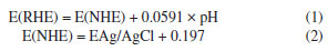 The XPS valence band spectrum (see Figure 9S, Supplementary Material) further indicates that the energy gap between the valence band (VB) of TiO2+Na3PO4 and the Fermi level is 2.32 eV. Assuming the flat band potential as the Fermi level of the n-type semiconductor, the VB position of Ti2O+Na3PO4 is calculated to be 2.4407 V (relative to RHE). Therefore, the calculated CB edge potential of TiO2+Na3PO4 is -0.7893 V (Figure 10S, Supplementary Material). The catalyst TiO2+Na3PO4 is capable of driving the photocatalytic reduction of CO2 to CO (ECO2/CO = -0.53 V vs. NHE).36 Density functional theory (DFT) calculation To thoroughly investigate the adsorption state of PO43- on TiO2 surfaces, as well as the impact of enhancing the surface microenvironment on water adsorption, we employed density functional theory (DFT) to calculate the binding energy of the PO43- modified TiO2 model system (Figure 4a). Additionally, we utilized Forcite to compute the probability of water molecules appearing around PO43-. The computational results indicated that the binding energy between PO43- and TiO2 was negative, suggesting that PO43- can stably modify the TiO2 surface (Figure 12S, Supplementary Material). Combined with previous XPS data, our findings revealed that the bonding of PO43- with TiO2 resulted in electrons transferring from TiO2 to PO43-, further confirming the charge transfer occurring at the interface between TiO2 and PO43-. Furthermore, PO43- bound to the TiO2 surface could accumulate more electrons, while the TiO2 surface lost electrons. This again demonstrated that modifying the TiO2 surface with PO43- was conducive to charge separation. We utilized the molecular dynamics (MD) simulations to create a discrete box model of PO43- and H2O, optimizing the model to obtain radial distribution functions (RDF). Our primary focus was on the RDF of Total (P-O) (Figure 4c), where the first peak (2-2.2) corresponded to the P-O bond. The second and third peaks (1.2~4.5) represented water molecules. The P-O radial distribution function indicated that there are two layers of bound water surrounding the PO43- ion. In the similar manner, the RDF of Total (P-H) showed the interaction between H2O and PO43- (Figure 4d). These results suggest that PO43- has a distinct attraction to water molecules, which may enhance water oxidation and facilitate the rapid transfer of electrons to the CO2 reduction pathway. To describe the CO2 adsorption and activation process on TiO2+Na3PO4, in situ CO2 adsorption diffuse reflectance infrared Fourier transform spectroscopy (DRIFTS) was conducted on the TiO2 + Na3PO4 sample under light illumination to explore the reaction mechanism. As shown in Figures 5a-5b, after CO2 adsorption reached saturation under dark conditions, *COOH (2933 cm-1)37 was generated on the surface of TiO2+Na3PO4. The appearance of the *COOH species indicates that CO2 activation is facilitated, meaning that TiO2+Na3PO4 is more likely to adsorb and activate CO2, consistent with the results in CO2-TPD (Figure 4S). After illumination, the peak in the range of 3500-3800 cm-1 on the TiO2+Na3PO4 sample38,39 weakens simultaneously, indicating that the adsorbed CO2 and hydroxyl species are engaged in the reaction. This implies that the remarkable performance of the TiO2+Na3PO4 composite material is largely due to the critical role of *COOH species in the activation process. Additionally, the presence of surface Lewis basic sites increases the likelihood of CO formation.
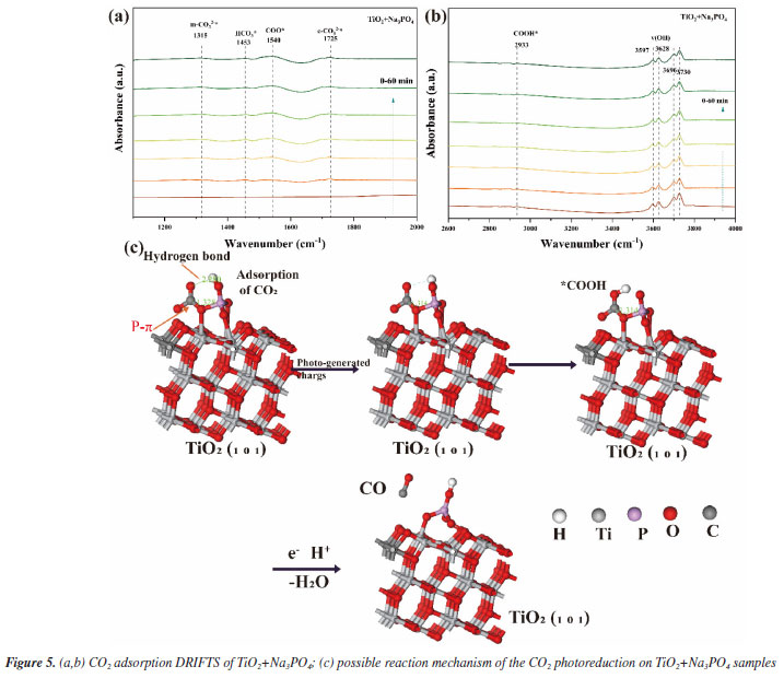
The process mechanism illustrated in Figure 5c involves four steps: (i) the reactant CO2 is adsorbed onto TiO2 + Na3PO4. The empty orbital of the carbon atom in CO2 hybridizes with the 2p orbital of the oxygen atom in PO43-. The hydrogen bond of the oxygen atom in CO2 interacts with the hydrogen atom (Figure 13S, Supplementary Material). (ii) Under light illumination, TiO2 generates photoelectrons and holes. The photo-generated electrons are transferred to the hydrogen bond of PO43- and the hydrogen atom in CO2. (iii) Through these electronic interactions, the intermediate active species *COOH is generated. (iv) An H+ attacks the oxygen atom of the *COOH intermediate, resulting in the formation of CO.
CONCLUSIONS This study focuses on the TiO2+Na3PO4 photocatalyst, which demonstrates exceptional performance in reducing CO2. The incorporation of PO43- creates a rapid charge transfer channel (P-Ti-O) at the TiO2 interface. Additionally, this modification enhances the adsorption and activation of CO2 at Lewis basic sites. The analysis of in situ CO2 adsorption using DRIFTS under light irradiation suggests a reaction mechanism. It indicates that the combined effect of the directional charge transfer channel and the presence of abundant active sites significantly boosts the photocatalytic activity of the TiO2+Na3PO4 photocatalyst in CO2 reduction.
SUPPLEMENTARY MATERIAL Supplementary material is available free of charge at http://quimicanova.sbq.org.br as PDF file.
ACKNOWLEDGMENTS The authors gratefully acknowledge support from the Fundamental Research Funds for the Central Universities (No. 21621401) and the Natural Science Foundation of Guangdong Province (2021A1515010390).
REFERENCES 1. Forkel, M.; Carvalhais, N.; Rödenbeck, C.; Keeling, R.; Heimann, M.; Thonicke, K.; Zaehle, S.; Reichstein, M.; Science 2016, 351, 696. [Crossref] 2. Li, C.; Pan, W.; Zhang, Z.; Wu, T.; Guo, R.; Small 2023, 19, 2300460. [Crossref] 3. Cho, K. M.; Kim, K. H.; Park, K.; Kim, C.; Kim, S.; Al-Saggaf, A.; Gereige, I.; Jung, H.-T.; ACS Catal. 2017, 7, 7064. [Crossref] 4. Xu, F.; Meng, K.; Cheng, B.; Wang, S.; Xu, J.; Yu, J.; Nat. Commun. 2020, 11, 4613. [Crossref] 5. Ruan, X.; Li, S.; Huang, C.; Zheng, W.; Cui, X.; Ravi, S. K.; Adv. Mater. 2024, 36, 2305285. [Crossref] 6. Wu, X.; Li, Y.; Zhang, G.; Chen, H.; Li, J.; Wang, K.; Pan, Y.; Zhao, Y.; Sun, Y.; Xie, Y.; J. Am. Chem. Soc. 2019, 141, 5267. [Crossref] 7. Zhang, S.-N.; Li, M.; Hua, B.; Duan, N.; Ding, S.; Bergens, S.; Shankar, K.; Luo, J.-L.; ChemCatChem 2019, 11, 4147. [Crossref] 8. Wang, Z.; Mahmood, A.; Xie, X.; Wang, X.; Qiu, H.; Sun, J.; Chem. Eng. J. 2020, 393, 124723. [Crossref] 9. Low, J.; Cheng, B.; Yu, J.; Appl. Surf. Sci. 2017, 392, 658. [Crossref] 10. Shen, Y.; Ren, C.; Zheng, L.; Xu, X.; Long, R.; Zhang, W.; Yang, Y.; Zhang, Y.; Yao, Y.; Chi, H.; Wang, J.; Shen, Q.; Xiong, Y.; Zou, Z.; Zhou, Y.; Nat. Commun. 2023, 14, 1117. [Crossref] 11. Yu, Y.; He, Y.; Yan, P.; Wang, S.; Dong, F.; PNAS 2023, 120, e2307320120. [Crossref] 12. Feng, C.; Bo, T.; Maity, P.; Zuo, S.; Zhou, W.; Huang, K.-W.; Mohammed, O. F.; Zhang, H.; Adv. Funct. Mater. 2024, 34, 2309761. [Crossref] 13. Zhang, L.; Li, Y.; Li, Q.; Fan, J.; Carabineiro, S. A. C.; Lv, K.; Chem. Eng. J. 2021, 419, 129484. [Crossref] 14. Wu, Y.; Hu, Q.; Chen, Q.; Jiao, X.; Xie, Y.; Acc. Chem. Res. 2023, 56, 2500. [Crossref] 15. Wang, W.; Deng, C.; Xie, S.; Li, Y.; Zhang, W.; Sheng, H.; Chen, C.; Zhao, J.; J. Am. Chem. Soc. 2021, 143, 2984. [Crossref] 16. Wang, T.; Chen, L.; Chen, C.; Huang, M.; Huang, Y.; Liu, S.; Li, B.; ACS Nano 2022, 16, 2306. [Crossref] 17. Ni, B.; Jiang, H.; Guo, W.; Xu, Q.; Min, Y.; Appl. Catal., B 2022, 307, 121141. [Crossref] 18. Ren, C.; Li, Q.; Ling, C.; Wang, J.; J. Am. Chem. Soc. 2023, 145, 28276. [Crossref] 19. Feng, Y.; Wang, C.; Cui, P.; Li, C.; Zhang, B.; Gan, L.; Zhang, S.; Zhang, X.; Zhou, X.; Sun, Z.; Wang, K.; Duan, Y.; Li, H.; Zhou, K.; Huang, H.; Li, A.; Zhuang, C.; Wang, L.; Zhang, Z.; Han, X.; Adv. Mater. 2022, 34, 2109074. [Crossref] 20. Xu, Q.; Zhang, L.; Cheng, B.; Fan, J.; Yu, J.; Chem 2020, 6, 1543. [Crossref] 21. Shi, Y.; Zhan, G.; Li, H.; Wang, X.; Liu, X.; Shi, L.; Wei, K.; Ling, C.; Li, Z.; Wang, H.; Mao, C.; Liu, X.; Zhang, L.; Adv. Mater. 2021, 33, 2100143. [Crossref] 22. Li, X.; Li, L.; Chen, G.; Chu, X.; Liu, X.; Naisa, C.; Pohl, D.; Löffler, M.; Feng, X.; Nat. Commun. 2023, 14, 4034. [Crossref] 23. He, Z.; Tang, J.; Shen, J.; Chen, J.; Song, S.; Appl. Surf. Sci. 2016, 364, 416. [Crossref] 24. Chang, X.; Wang, T.; Gong, J.; Energy Environ. Sci. 2016, 9, 2177. [Crossref] 25. Tseng, I.-H.; Yang, Y.-H.; Chen, Y.-T.; Hsu, L.-C.; ACS Appl. Mater. Interfaces 2023, 15, 5038. [Crossref] 26. Qin, X.; Jing, L.; Tian, G.; Qu, Y.; Feng, Y.; J. Hazard. Mater. 2009, 172, 1168. [Crossref] 27. Ding, Z.; Lu, G. Q.; Greenfield, P. F.; J. Phys. Chem. B 2000, 104, 4815. [Crossref] 28. Shang, H.; Jia, H.; Zhang, W.; Li, S.; Wang, Q.; Yang, Q.; Zhang, C.; Shi, Y.; Wang, Y.; Li, P.; He, Y.; Xiao, S.; Wang, D.; Zhang, D.; Environ. Sci. Technol. 2023, 57, 20400. [Crossref] 29. He, Y.; Zhang, L.; Teng, B.; Fan, M.; Environ. Sci. Technol. 2015, 49, 649. [Crossref] 30. Ma, H.; Wang, X.; Tan, T.; Zhou, X.; Dong, F.; Sun, Y.; Appl. Catal., B 2022, 319, 121911. [Crossref] 31. Södergren, S.; Siegbahn, H.; Rensmo, H.; Lindström, H.; Hagfeldt, A.; Lindquist, S.-E.; J. Phys. Chem. B 1997, 101, 3087. [Crossref] 32. Puziy, A. M.; Poddubnaya, O. I.; Ziatdinov, A. M.; Appl. Surf. Sci. 2006, 252, 8036. [Crossref] 33. Hirao, A.; Nishizawa, H.; Phys. Rev. B 1996, 54, 4755. [Crossref] 34. Macdonald, D. D.; Electrochim. Acta 2006, 51, 1376. [Crossref] 35. Zhang, G.; Zhu, J.; Xu, Y.; Yang, C.; He, C.; Zhang, P.; Li, Y.; Ren, X.; Mi, H.; ACS Catal. 2022, 12, 4648. [Crossref] 36. Fu, J.; Jiang, K.; Qiu, X.; Yu, J.; Liu, M.; Mater. Today 2020, 32, 222. [Crossref] 37. Zhou, W.; Chen, K.; Ke, Q.; Wang, H.; Chen, X.; Liu, Y.; Cui, G.; Weng, X.; Zhou, Y.; Lu, H.; J. Rare Earths 2023, 41, 881. [Crossref] 38. King, S. T.; Garces, J. M.; J. Catal. 1987, 104, 59. [Crossref] 39. Kondo, J. N.; Yang, S.; Zhu, Q.; Inagaki, S.; Domen, K.; J. Catal. 2007, 248, 53. [Crossref]
Editor handled this article: Giovanna Machado |

On-line version ISSN 1678-7064 Printed version ISSN 0100-4042
Qu�mica Nova
Publica��es da Sociedade Brasileira de Qu�mica
Caixa Postal: 26037
05513-970 S�o Paulo - SP
Tel/Fax: +55.11.3032.2299/+55.11.3814.3602
Free access